


Content last revised on September 18, 2026
VSKDS201/045 Operational Boundaries: Evaluating 6-Pulse and 12-Pulse Bridge Configuration Limits
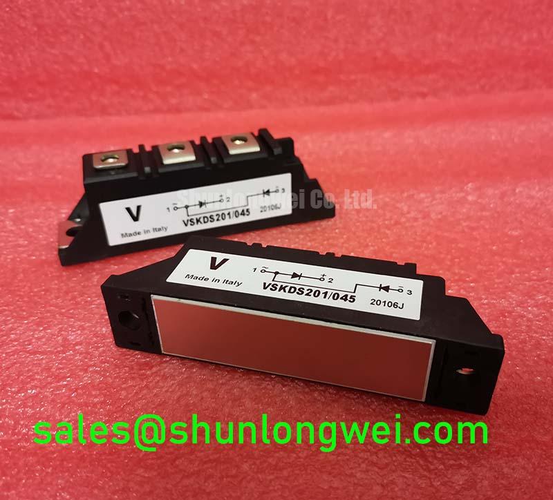
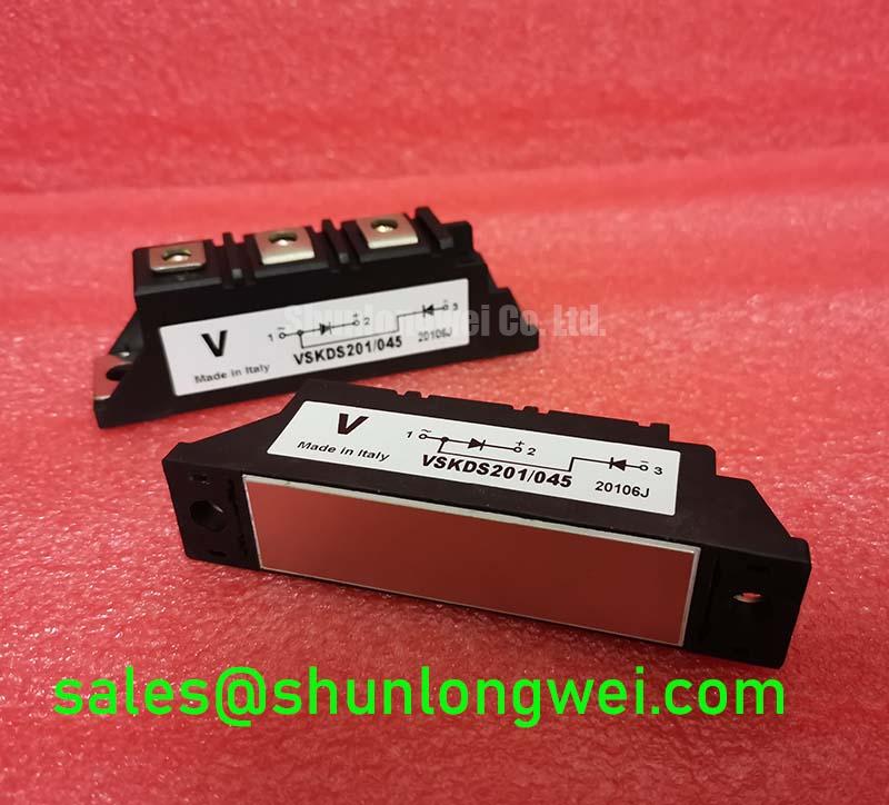
Before energizing a replacement, isolate the VSKDS201/045, confirm its terminal markings against the original rectifier drawing, and record a cold-state resistance and diode-test baseline with the module disconnected from every external circuit. The Vishay device is specified as a 1600 V, 200 A Thyristor/Diode Module in a Power Block / Bridge Case. Those three values are Official Specification data supplied for this product and should be checked against the equipment bill of materials before installation.
For a high-current green hydrogen electrolyzer DC power rectifier, the VSKDS201/045 may be evaluated within either a six-pulse or twelve-pulse bridge arrangement, subject to the complete converter schematic and the original equipment specification. A six-pulse bridge normally uses one three-phase bridge path, while a twelve-pulse arrangement uses phase-shifted secondary supplies and two rectifier bridges. The interphase transformer, where fitted, must be assessed for current sharing, insulation coordination, thermal loading, and its response to unequal bridge conduction.
The module’s 1600 V rated voltage and 200 A rated current define important component-level boundaries, but they do not establish the allowable DC output current of a complete rectifier. System engineers should verify commutation overlap, transformer impedance, cooling conditions, repetitive peak current, surge current, and the applicable fuse coordination data from the Vishay documentation for the exact configuration. No fuse I²t value or surge-current figure is assumed here because those values were not provided in the product data supplied for this page.
During incoming inspection, use the diode-test function only after confirming the internal circuit topology from the original drawing. Measure each accessible semiconductor path in both polarities and compare corresponding paths rather than treating one meter reading as a universal pass or fail threshold. Gate or auxiliary terminals, if present in the installed bridge arrangement, should be identified from the equipment schematic; this page does not assign an unverified pinout to the Power Block case.
Terminal preparation is part of the electrical test. Clean contact surfaces, inspect the busbar interface, and check that the clamping hardware is appropriate for the original assembly. The manufacturer’s installation instructions and the equipment service manual take precedence for mounting torque. A generic torque value must not be presented as an official VSKDS201/045 parameter.
For a neutral compatibility comparison during field planning, engineers may review VS-ST730C18L0. It should be evaluated by its own voltage, current, case, terminal, thermal, and mechanical data rather than treated as an automatic substitute.
VSKDS201/045 Thermal-Electrical Optimization: AC Line Surge Immunity and Lightning Transient Tuning
AC input protection for a rectifier begins with the installation category, transformer impedance, prospective fault current, and the surge environment at the equipment location. IEC 61000-4-5 testing may be relevant to the assembled power system, but a discrete thyristor/diode module does not independently establish compliance with the complete system test. The integrator should coordinate upstream fuses, disconnects, surge protective devices, and the rectifier’s thermal path using measured or documented system conditions.
MOV selection is a Design Consideration rather than a fixed VSKDS201/045 specification. The selected device must tolerate the normal line voltage and expected temporary overvoltage while clamping the transient below the rectifier’s verified repetitive voltage boundary. Its energy rating, short-circuit behavior, coordination with upstream protection, and degradation after repeated events should be reviewed together. An MOV installed directly across an AC input without checking leakage, fault clearing, and phase-to-phase or phase-to-ground topology can create a new protection problem.
RC snubbers can reduce high-frequency voltage ringing across semiconductor junctions, but the resistor, capacitor, damping behavior, dielectric class, and pulse current must be determined from the measured commutation waveform. This is an Engineering Recommendation for system tuning, not an official parameter of the Vishay module. Use a suitably rated differential probe and confirm the waveform at the module terminals, because a control-cabinet measurement may hide busbar inductance and local overshoot.
Long motor or converter cables can behave as transmission lines. Reflected-wave voltage may create a second peak at the load or rectifier interface, depending on cable length, termination, impedance, and switching edge. The remedy should be selected from measured waveforms and the complete cable topology. Designers should minimize parasitic loop inductance, coordinate surge absorption with the source impedance, and verify peak voltage against the module’s electrical boundary during controlled tests.
Reverse-recovery behavior of an associated diode path can also influence EMI. The softness factor of a particular diode must come from its applicable datasheet or laboratory waveform; it should not be inferred from the VSKDS201/045 part number alone. A Rogowski coil can help observe fast current transients without inserting a significant shunt impedance, as described in this Rogowski Coil Principle reference.
Transient Dynamics and Electrical Design: Critical Rate of Rise of Off-State Voltage
In a phase-controlled bridge, an excessive rate of rise of off-state voltage may contribute to unintended thyristor triggering, especially when the gate circuit, commutation path, and physical layout are not adequately coordinated. The VSKDS201/045 product data supplied here confirms voltage, current, and case type, but does not provide a verified critical dv/dt value, gate trigger specification, or snubber network value. Those parameters must be taken from the relevant Vishay datasheet revision or measured during qualification.
Begin troubleshooting by comparing the voltage waveform directly across the suspect module with a known-good bridge position. Inspect the gate wiring for excessive loop area, unintended coupling from the anode or cathode busbar, and poor reference continuity. The gate circuit should be treated as a controlled signal path, not as an incidental short wire. Where a saturable reactor or other series impedance is considered, its saturation behavior, pulse current, thermal duty, and recovery characteristics must be evaluated against the actual bridge waveform.
Parallel semiconductor paths require particular care. Positive temperature coefficient behavior can support static current sharing in some operating regions, but dynamic sharing is controlled by layout symmetry, commutation timing, stray inductance, thermal coupling, and device matching. When multiple modules are paralleled, designers should measure current distribution under startup, steady-state, and transient conditions rather than assuming equal sharing from identical labels.
The same principle applies to auxiliary wiring. A Kelvin emitter connection is an IGBT-specific term and must not be assigned to this thyristor/diode module without an official terminal definition. If the equipment includes a separate auxiliary or gate return terminal, keep its routing separated from high-current commutation conductors and verify the reference potential at the device pins.
For broader rectifier layout, protection, and switching-stress considerations, the Power Electronics Masterclass provides useful system-level context. Its guidance does not replace the product-specific Vishay documentation.
Benchtop Waveform Tuning: Post-Surge Reverse Voltage Blocking Evaluation
After an AC surge or high-current event, do not reapply reverse voltage until the bridge has been isolated, discharged, inspected, and compared with a cold-state baseline. A visual inspection should include the Power Block / Bridge Case, terminal hardware, busbar contact area, signs of mechanical displacement, and any discoloration around the mounting interface. Static resistance and diode-test comparisons can identify a changed conduction path, but they cannot by themselves confirm dynamic blocking capability.
The specified 1600 V voltage rating is an Official Specification boundary for the VSKDS201/045. It is not a permission to test the component at that voltage on an open bench. A controlled high-voltage test, if required by the service procedure, must use appropriate current limiting, guarded connections, discharge controls, and an approved test method. The engineer should also verify junction-temperature conditions before returning the bridge to service, since prior surge stress may have changed leakage or thermal behavior without producing an obvious external mark.
Do not infer the module’s non-repetitive surge current or 10 ms half-cycle ITSM value from its 200 A rated current. ITSM, I²t coordination, recovery conditions, and permitted repetition are separate datasheet characteristics and must be confirmed from the exact Vishay technical document. The same caution applies to fuse selection: use the manufacturer’s coordination table where available, then validate the complete fuse, busbar, transformer, and module combination under the intended fault-clearing conditions.
Bench Tip: Wear appropriate ESD protection, keep the module fully isolated, and compare every cold-state measurement with a known-good reference before reconnecting control or power wiring.
Vishay’s Industrial Power MOSFETs technical resource can help distinguish MOSFET-specific switching information from thyristor and diode module data. For the VSKDS201/045 itself, procurement and installation decisions should remain tied to the verified 1600 V, 200 A, Power Block / Bridge Case specification and the original rectifier’s electrical, thermal, mechanical, and protection documentation.