

Content last revised on November 13, 2026
Field Diagnostics & Commissioning: Interphase Transformer Current Balancing in T70HFL20S02 Topologies
Isolate the rectifier, verify that stored energy has discharged, and disconnect parallel current paths before checking the T70HFL20S02 with a multimeter. Record forward and reverse readings against the terminal diagram and a known-good assembly under comparable conditions. A cold resistance check can reveal an abnormal conduction path, but it cannot establish blocking capability, surge endurance, or reverse-recovery performance under load.
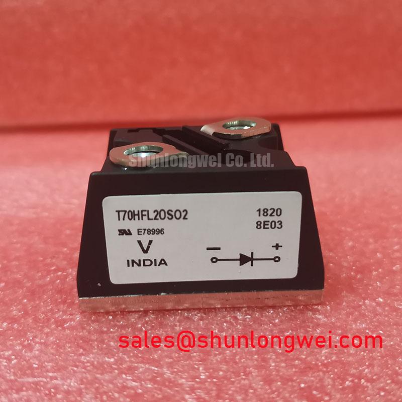
The product specification baseline identifies Manufacturer: Vishay, Part Number: T70HFL20S02, Average Forward Current (IF(AV)): 70.0 A under the specified datasheet conditions, Package: Module, and Device Type: Fast-Recovery Diode Module. These identifiers anchor the component assessment; operating acceptance also depends on the circuit connections and the conditions attached to its electrical ratings.
Trace each bridge branch through its transformer winding, semiconductor terminals, fuse, and DC connection before investigating interphase transformer current imbalance. As a Design Consideration, a six-pulse bridge and a twelve-pulse assembly require different commissioning checks: the latter depends on the intended transformer phase displacement and bridge interconnection. An interphase transformer belongs to a suitable parallel-bridge arrangement, not automatically to every twelve-pulse circuit.
For equipment targeting kiloampere-level output, assess current at the individual semiconductor branch rather than assigning the complete rectifier output to this 70.0 A module. Where an interphase transformer is fitted, compare bridge currents at the same load point and examine winding polarity, connection resistance, transformer secondary balance, and firing synchronization if the assembly includes controlled devices. Unequal sharing can have several interacting causes; a warm branch alone does not establish a defective semiconductor.
Engineering Recommendation: isolate external parallel paths before comparing diode forward and reverse readings with an equivalent healthy branch. Use the documented terminal identification rather than inferring connections from housing position. This diode module has no thyristor gate to test. Any subsequent powered assessment should follow the equipment service procedure.
Keep a fuse coordination record alongside the commissioning measurements. It should compare fuse total-clearing I²t with the semiconductor withstand specification under compatible waveform, voltage, and temperature conditions. Include prospective fault current and protective-device interruption capability. The T1503N75TS04 can be reviewed separately when assessing complementary rectifier-stage components, with its own circuit role and protection requirements; it is not an implied replacement.
Preventing Spurious Faults: Mechanical Mounting Torque Sequence and Thermal Guidelines for T70HFL20S02
Check heatsink flatness, mounting-face cleanliness, and terminal alignment before tightening the module. As a Design Consideration, uneven contact pressure can increase interface thermal resistance and distort the mounting assembly. Follow the applicable mounting sequence, keeping the module seated without using terminal hardware to pull misaligned busbars into position.
Evaluate junction-to-case thermal resistance separately from the case-to-heatsink interface. R_th(j-c) describes a specified device thermal path; it does not include installation-dependent paste coverage or heatsink performance. Do not assume a copper baseplate construction from the module designation. Apply the approved thermal interface material according to its installation instructions, avoiding contamination, trapped debris, and unsupported thickness targets.
The comparison below separates the supplied product baseline from the additional information needed for a service substitution. The linked 85HF120 is a comparison reference, not a declaration of matching topology, mounting, or electrical performance.
| Assessment item | T70HFL20S02 | 85HF120 comparison requirement |
|---|---|---|
| Manufacturer | Vishay | Check manufacturer documentation |
| Average Forward Current (IF(AV)) | 70.0 A under the specified datasheet conditions | Compare rating definitions and thermal conditions |
| Package | Module | Compare outline and mounting arrangement |
| Device type | Fast-Recovery Diode Module | Establish circuit, recovery-characteristic, and terminal compatibility |
| Reverse voltage, IFSM, I²t, R_th(j-c), mounting torque | Consult datasheet | Compare documented limits individually |
Maintenance Note: Monitor terminal temperature rise under comparable load and inspect cooling airflow before attributing recurring thermal trips to the module. Set inspection intervals around contamination, operating duty, and observed interface condition rather than an invented universal replacement period. During maintenance, inspect thermal material for deterioration and use calibrated tools for specified fastener checks. After cold storage or temperature transitions, address condensation before energization.
Transient Dynamics & Electrical Design: AC-to-DC Operation with T70HFL20S02
Record DC output and AC input current together when evaluating rectifier operation. The T70HFL20S02 is a diode module and does not provide firing-angle control. If the surrounding assembly includes separately controlled thyristors, record their firing synchronization as well. As a Design Consideration, delaying thyristor firing changes the available conduction interval, but the resulting transfer characteristic depends on bridge topology, load continuity, commutation overlap, and freewheeling paths. A mixed thyristor/diode circuit should not be assessed using the unrestricted characteristic of a fully controlled bridge.
Where a separate thyristor-controlled stage is present, distinguish displacement effects from waveform distortion when assessing power factor and reactive demand across a firing-angle sweep. Use the controller’s permitted operating range rather than imposing a generic angle sweep. A high-current green hydrogen electrolyzer DC power rectifier is one potential compatibility assessment, subject to branch-current capability, protection coordination, cooling, and the equipment’s required control behavior.
For transient assessment, capture terminal stress with suitable instrumentation and compare it with documented reverse-voltage, recovery, and surge conditions. The IGBT Modules and IPMs Technical Reference offers broader power-stage context, not acceptance limits for this diode module. The external Shindengen Power Semiconductor Modules & Diodes resource provides general semiconductor context, not Vishay-specific ratings. After a surge event, determine restart readiness from the protection sequence, thermal condition, and inspection results; IFSM is not a repetitive operating allowance or a fixed junction-temperature recovery timer.