
Content last revised on October 2, 2026
Assembly Integrity & Layout Architecture: Installing the 90MT160KPBF Rectifier Module
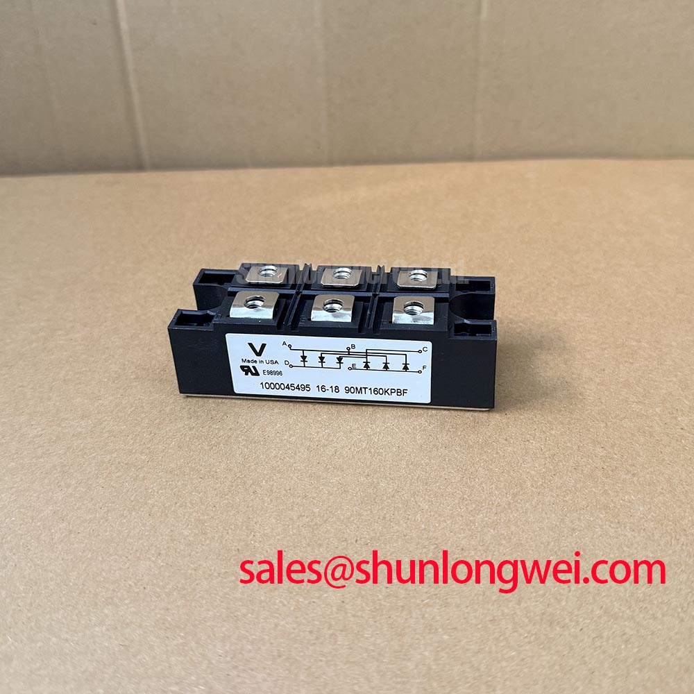
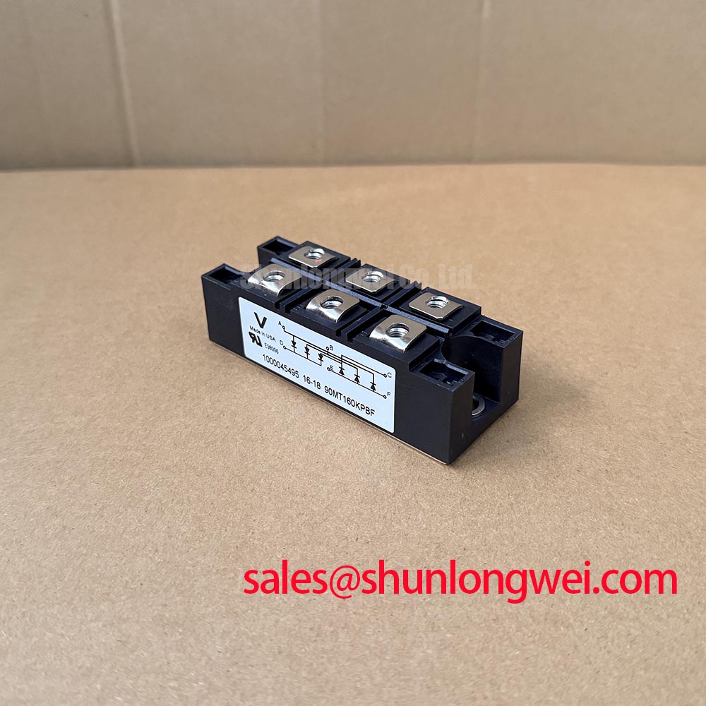
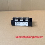
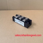
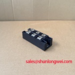
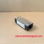
Measure the disconnected power path for unintended low impedance, inspect every accessible terminal and mounting surface, and compare the mechanical position of the replacement module with the original assembly before applying voltage. The Vishay 90MT160KPBF is a three-phase bridge rectifier module, not a gate-controlled inverter switch. It is a 1600 V, 90 A class device; the applicable current rating and its temperature conditions must be checked in the manufacturer’s documentation before use.
Begin the compatibility check at the system interface. Trace the three AC input connections, the positive and negative DC output connections, and the protective earth path. The replacement must match the original terminal functions and mechanical orientation. A physically similar module can still be unsuitable when its terminal order, electrical ratings, or thermal mounting arrangement differs.
In an inverter or energy storage assembly, the rectifier may be part of an AC-to-DC supply path. Its presence does not make that path bidirectional: a diode bridge cannot be commanded to transfer power from the DC side back to the AC side. Confirm the module’s role in the original equipment circuit before evaluating a replacement.
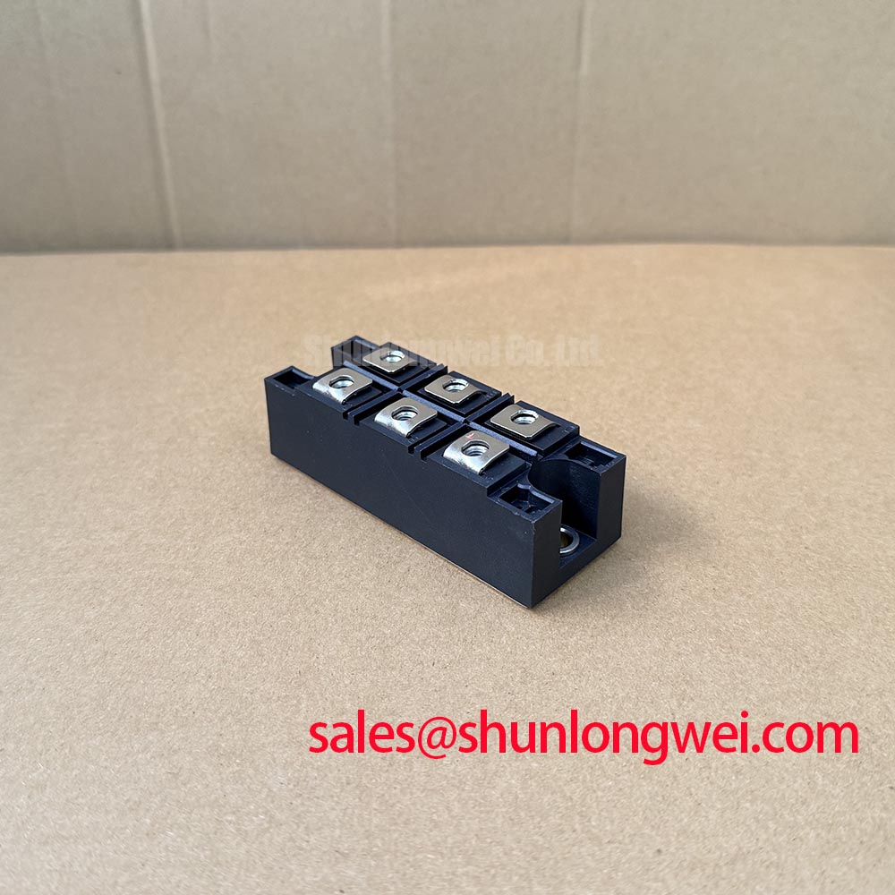
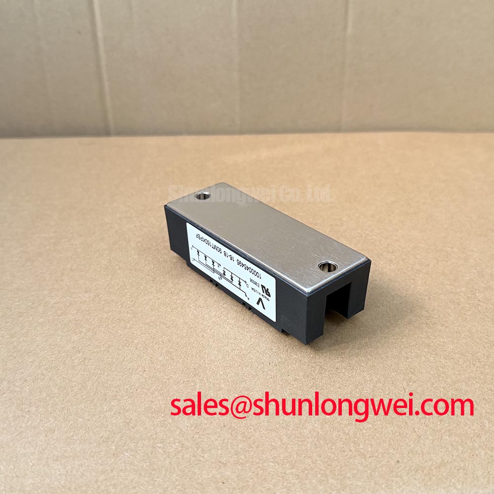
Check the mounting face for contamination, raised burrs, uneven contact, or mechanical distortion. The heat transfer interface should be continuous and uniform across the intended contact area. Follow the manufacturer’s and equipment maker’s instructions for mounting hardware, thermal interface material, and tightening sequence. Excessive or uneven force can damage the package or impair thermal contact.
Keep high-current connections short and mechanically secure while maintaining the required insulation distances. Inspect bolted joints, conductor condition, and busbar alignment. The final clearance and creepage arrangement must be established from the system working voltage, insulation coordination, operating environment, and applicable equipment standard.
Field Alert: Isolate and verify the AC input, DC link, and auxiliary supplies before disconnecting module wiring. A DC-link capacitor can remain charged after the input supply is removed.
Field Diagnostics & Commissioning: Checking the Rectifier and Thermal Path
With the module safely isolated from circuitry that could affect the reading, compare diode-test results across the intended AC-to-DC conduction paths. A diode bridge should conduct through its expected paths in one test polarity and block in the reverse polarity. Connected capacitors, sensing networks, and other components can make an in-circuit reading misleading; a single resistance measurement is not proof of module health.
During commissioning, record load current, case temperature at the specified measurement location, heat sink condition, and fan or coolant state. Case temperature alone does not reveal instantaneous junction temperature. Junction-temperature estimates require the applicable manufacturer thermal data and a loss estimate based on the actual operating conditions.
Repeated overloads require particular attention because the semiconductor junction can heat faster than the heat sink or a slow service display responds. Compare measured current and temperature with the confirmed device ratings and the equipment’s protection settings. If one connection runs hotter than comparable connections, inspect contact resistance and cooling before assigning the cause to the module.
For service records, capture the module identification, installation orientation, terminal map, heat sink condition, electrical test results, load current, and thermal response. This creates a useful field baseline without assigning an unsupported service-life figure.
Assembly Integrity & Layout Architecture: Managing Rectifier Current Paths
Inspect the complete rectifier current path, including the AC supply connections, module terminals, DC-link capacitor, busbars, connection hardware, and measurement points. Loose joints and unnecessarily long current paths can increase heating and transient voltage stress.
Keep outgoing and returning high-current conductors appropriately arranged while preserving insulation clearance and service access. Place DC-link components as required by the converter design, and verify the finished assembly under its intended load conditions. No specific commutation-loop inductance target can be assigned to the 90MT160KPBF from its part number alone.
When a snubber or surge-protection network is present in the equipment, inspect its components, mounting location, and connections as a complete network. Check for cracked components, loose fasteners, and heat discoloration after a field failure. Its component values and voltage limits must be verified against the original circuit design.
The Power Electronics Masterclass offers broader background on power-stage reliability. Use the rectifier manufacturer’s documentation and the original equipment circuit information for decisions about this module.
Transient Dynamics & Electrical Design: Verifying System Suitability
Measure the AC input, DC output, and rectifier current during a controlled commissioning test. Compare the results with the equipment baseline, paying attention to input imbalance, DC-link ripple, abnormal heating, and voltage transients. Use measurement equipment and procedures suitable for the circuit’s voltage and fault-energy levels.
For an industrial inverter or energy storage repair, verify the rectifier against the equipment’s AC input, DC-link voltage, load current, surge conditions, cooling system, and insulation requirements. A matching voltage and current class alone does not establish that a replacement is interchangeable; terminal configuration, mounting, and the applicable rating conditions also matter.
Gate resistance, Miller behavior, dead time, and gate-driver protection settings apply to controlled switches elsewhere in a converter, not to the diode bridge itself. Diagnose those circuits separately if the equipment contains them. After commissioning, retain the electrical measurements and thermal observations as a baseline for future service work.