

Content last revised on October 27, 2026
Transient Dynamics & Electrical Design: Auxiliary Kelvin Emitter vs Main Power EMI on A50L-1-0230
With the DC link isolated and its discharge verified, trace the gate-driver return on the A50L-1-0230 assembly before reconnecting the power stage. A return connected through the load-current path can distort the gate voltage seen by the switching device, so terminal identification belongs ahead of powered fault reproduction.
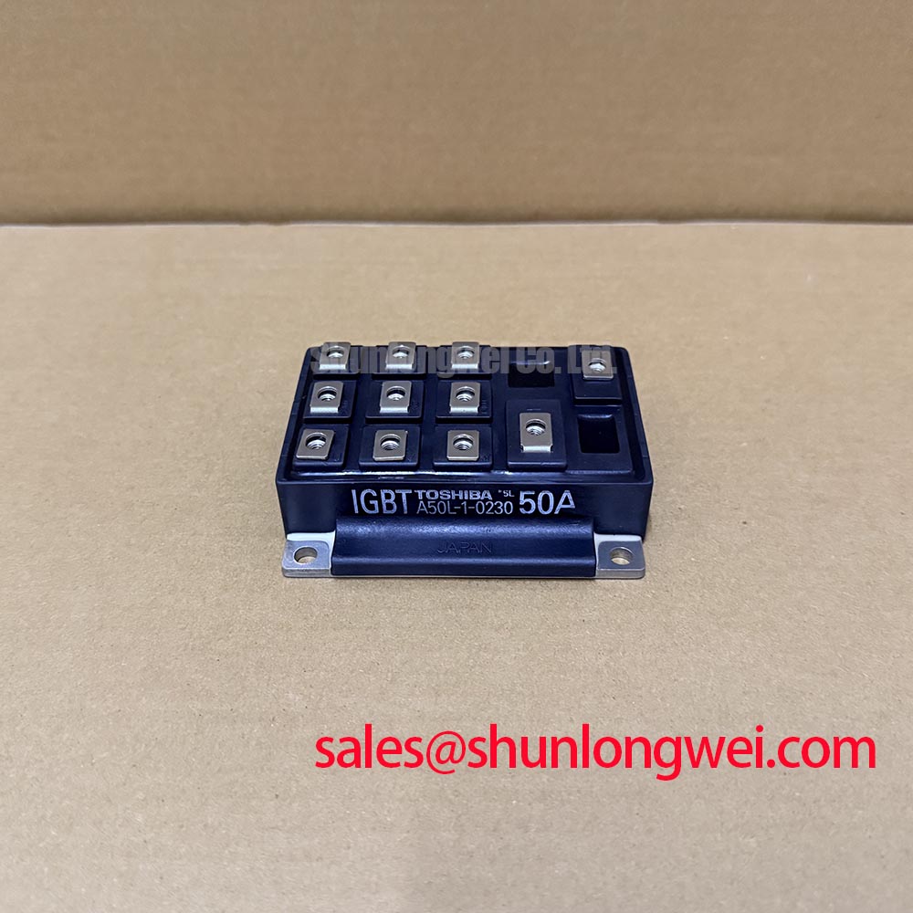
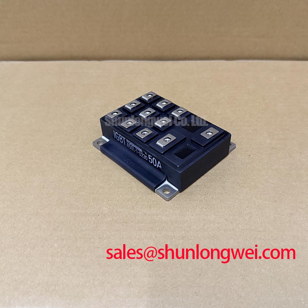
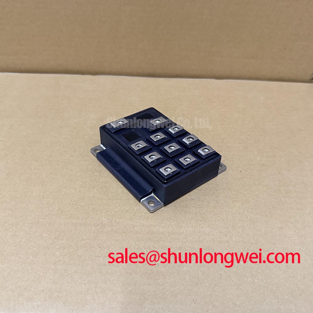
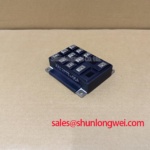
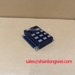
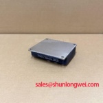
The Fuji Electric A50L-1-0230 is an IGBT Module with the supplied product specification identifying a Dual Half-Bridge IGBT topology and Fuji Power Module package. These identity details establish the component category; they do not establish its terminal map, drive requirements, or mechanical interchangeability. For maintenance planning, retain the equipment circuit diagram, module connection drawing, and mounting instructions with the replacement work order.
Trace the main emitter connection separately from the driver return, using the equipment schematic and the module terminal drawing rather than terminal size or position. Design Consideration: a dedicated auxiliary emitter connection, where explicitly documented, gives the driver a reference separated from much of the load-current path. The supplied A50L-1-0230 specification does not establish such a terminal, so a small connection must not be assigned that function by appearance.
Shared emitter-path inductance develops a transient voltage during rapid current changes. That voltage can alter the effective gate-to-emitter drive and complicate interpretation of a nuisance trip. During an authorized switching test, measure the gate waveform at the documented device connections with a suitable differential or isolated measurement arrangement. Comparing only the driver output to its local supply return can overlook voltage developed between the driver board and module.
Engineering Recommendation: keep the outgoing gate conductor and its documented return close together, separate them from high-current commutation paths, and preserve the equipment’s specified electrical clearances. Clearance requirements depend on the assembly voltage, insulation arrangement, contamination conditions, and applicable equipment requirements; they are not determined by this product name. Inspect repaired harness routing as carefully as the driver board itself.
If false triggering is suspected, compare the off-state gate waveform with the opposite switch’s commutation event. Check probe placement and common-mode measurement capability before interpreting a narrow spike as actual gate excitation. Miller coupling through collector-to-gate capacitance can contribute to unwanted turn-on, but the relevant capacitance and gate-charge characteristics must come from device documentation. An active Miller clamp, if present in the driver design, should be checked for correct connection and operation rather than assumed to compensate for a poor return path.
Preventing Spurious Faults: Antiparallel Freewheeling Diode Reverse Recovery Guidelines for A50L-1-0230
Correlate current overshoot with the commutation event before changing a snubber or gate resistor. Design Consideration: where an antiparallel freewheeling diode is documented in the power-stage circuit, its reverse recovery can contribute to turn-on current peaks and switching-node ringing. The A50L-1-0230 identity specification alone does not establish a diode recovery characteristic or an internal diode arrangement.
Observe the relevant current and switching-node voltage together under controlled operating conditions. Recovery behavior changes with operating current, temperature, and the imposed commutation rate, so waveforms taken under different conditions are not directly interchangeable. A sharp current transition can excite parasitic inductance and capacitance, but ringing can also be influenced by busbar geometry, capacitor connections, and measurement setup. Preserve those conditions when comparing the repaired assembly with an approved reference.
Engineering Recommendation: consider turn-on gate-resistance adjustment or an RC snubber only within the equipment’s validated design process. Slowing turn-on can reduce commutation severity while increasing switching loss; a snubber introduces its own dissipation and voltage-stress requirements. Component values should follow measured behavior and thermal assessment, not a generic prescription attached to the replacement module.
For cross-model assessment, the 2MBI50-120 provides a separate Fuji module reference, not an approved drop-in replacement. The comparison below separates established A50L-1-0230 identity information from the documentation needed to assess interchangeability.
| Selection item | A50L-1-0230 | 2MBI50-120 comparison requirement |
|---|---|---|
| Manufacturer | Fuji Electric | Fuji Electric; match the complete part designation |
| Product category | IGBT Module | Check the model-specific datasheet |
| Topology | Dual Half-Bridge IGBT, supplied specification | Compare the complete internal circuit and terminal map |
| Package | Fuji Power Module, supplied specification | Compare mounting dimensions and terminal positions |
| Collector-emitter voltage and collector current | Consult Datasheet | Consult Datasheet; do not infer ratings from the model name |
| Replacement status | No drop-in replacement established | Requires electrical, mechanical, thermal, and driver assessment |
Parallel operation needs a separate assessment. A positive temperature coefficient of on-state voltage can assist static current sharing only within the operating region where the particular device exhibits that behavior; it is not an established A50L-1-0230 characteristic here. Symmetrical power connections and comparable gate paths remain relevant design considerations, while dynamic sharing requires waveform assessment rather than inference from equal conductor lengths alone.
When reviewing adjacent conversion stages, identify each module by its actual circuit role. The 2MBI300NK-060 is another module reference for a separate switching-stage assessment, not evidence of a compatible rectifier or complementary device. Fuji Electric’s brake chopper IGBT module information also helps distinguish a dedicated chopper function from other converter positions without assigning that function to this model.
A50L-1-0230 Circuit Protection & Reliability: Calibrating Floating Gate Bias Supply Decoupling
Check floating driver-supply behavior during startup, shutdown, and fault reset before authorizing DC-link energization. Engineering Recommendation: the control sequence should inhibit switching until the required driver rails and protection signals are valid, and should preserve a defined off-state during supply collapse. The permissible bias levels and sequencing intervals belong to the module-and-driver combination; a negative gate bias is not a confirmed requirement of the supplied A50L-1-0230 specification.
Inspect local decoupling connections for looseness, damaged joints, and changes introduced during previous repairs. Measure the floating supply at the driver’s supply and return connections while observing the gate command. A stable auxiliary supply at the cabinet distribution point does not demonstrate stability at the switching driver. Rail disturbance synchronized with a switching edge calls for investigation of local current paths, decoupling condition, and measurement coupling.
Verify undervoltage lockout against the driver documentation, including what happens to the gate output as the supply approaches its operating boundary. Check the interaction between fault latching, controller reset, and renewed pulse enable. Intermittent startup faults should be investigated across the actual sequence rather than bypassed by extending a delay without identifying which signal is arriving late.
Dead time should prevent simultaneous conduction without introducing unnecessary distortion or diode conduction. Its assessment must include propagation-delay differences, turn-off behavior, temperature effects, and the driver’s fault response. Do not insert an arbitrary microsecond buffer: the equipment engineer should validate the interval from the actual switching behavior. Where active clamping is fitted, assess its interaction with gate limits and fault turn-off rather than treating it as an independent guarantee of protection.
For background when interpreting switching waveforms and electrical stress, The Ultimate IGBT Knowledge Base provides supporting principles, not model-specific acceptance limits. Fuji Electric’s IGBT module information, including its X-Series families offers manufacturer context without establishing this module’s generation or characteristics. Potential evaluation in commercial string inverters or micro-grid energy-storage converters remains conditional on the complete power-stage and protection requirements.
A50L-1-0230 Thermal-Electrical Optimization: Baseplate Convexity Inspection Practical Tuning
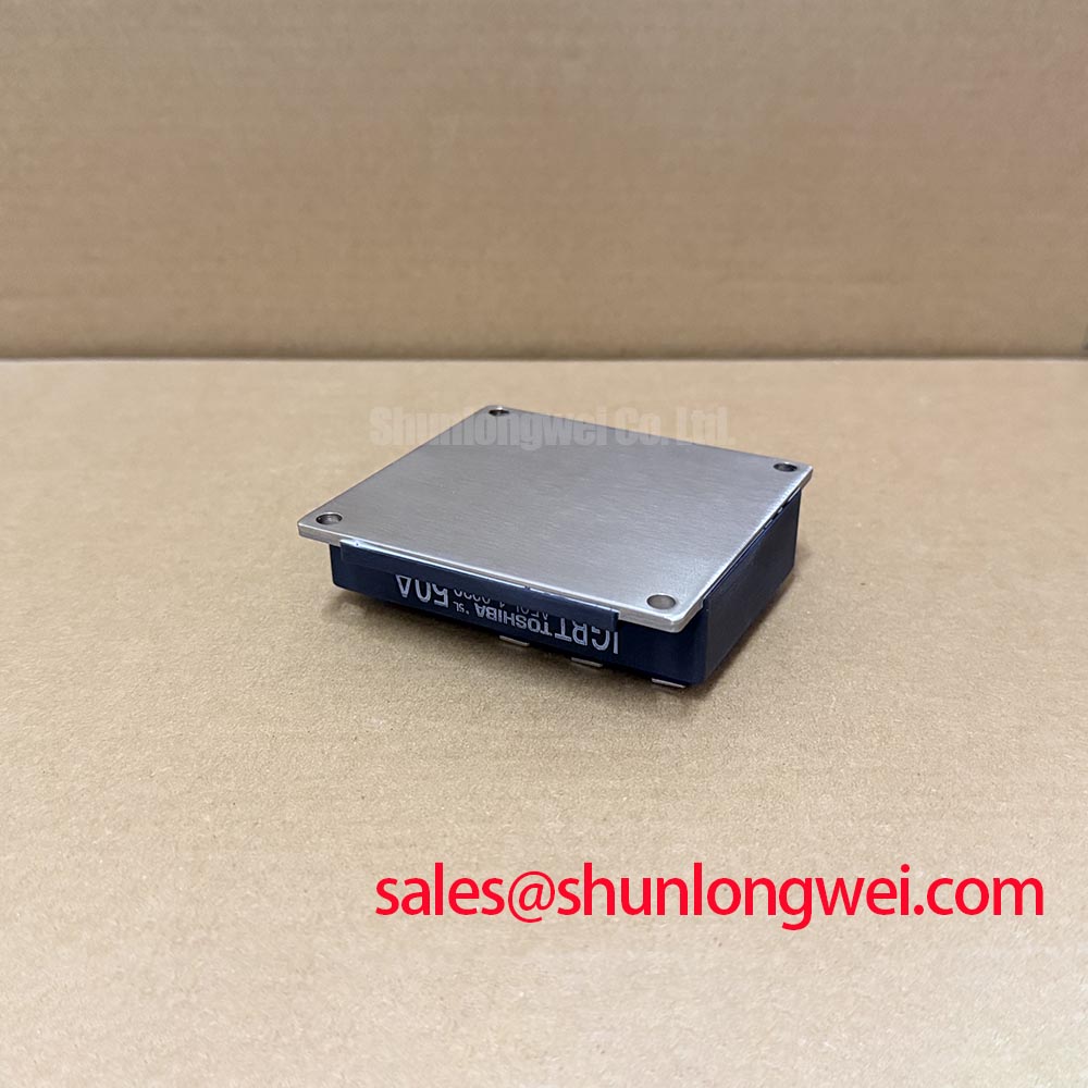
Inspect the module mounting surface and heatsink contact area for contamination, burrs, corrosion, and evidence of uneven contact before renewing the thermal interface. Design Consideration: mounting-surface shape affects contact pressure and heat transfer, but copper construction, specified convexity, and a particular interface thickness are not established A50L-1-0230 properties. Assess surface geometry against the applicable mechanical drawing instead of attempting to flatten the module by additional bolt load.
Use the specified mounting hardware and a calibrated torque tool. Where the assembly instructions call for staged cross-pattern tightening, follow that sequence to distribute loading rather than fully tightening one corner first. Select interface material and application thickness from the approved assembly instructions, accounting for surface condition and material behavior. A generic thickness target cannot establish adequate contact for this package.
Do not transfer press-pack procedures, disc-spring preload settings, or double-sided cooling practices to a bolted module assembly without explicit mechanical documentation. These arrangements use different loading paths. Existing spring washers or other load-control hardware should be retained or replaced according to the equipment specification, not supplemented to compensate for an unexplained temperature rise.
Maintenance Note: Trend terminal temperature rise under comparable load conditions and check cooling-air passages during scheduled inspections. Set cleaning and interface-inspection intervals from contamination exposure, operating duty, and observed condition rather than an invented service-life figure. Degraded airflow, terminal contact resistance, and mounting-interface deterioration deserve separate checks because similar temperature symptoms can originate from different locations.
After a shutdown in humid conditions, inspect for moisture and allow the assembly to reach the equipment’s permitted operating condition before energization. Following reassembly, record ambient conditions, cooling operation, load, and accessible temperature measurements so later inspections have a meaningful baseline. If one contact region remains hotter than comparable connections, investigate connection condition and current distribution before applying additional torque.