

Content last revised on October 11, 2026
AUO B104SN01-V2 LCD/HMI Panel Identification and Installation
- Confirm the part marking B104SN01-V2 and AUO manufacturer identification before installation.
- Compare the replacement panel’s mechanical envelope, mounting holes, connector position, and bezel clearance with the original display.
- Inspect the controller cable and mating connector for contamination, skewed contacts, or incomplete locking.
- Apply ESD controls before handling the TFT-LCD active matrix color display module.
B104SN01-V2 is an AUO industrial grade LCD/HMI panel classified as a TFT-LCD active matrix color display module. The confirmed product baseline describes a standard form factor and decoded baseline configuration. The supplied factory parameter set does not establish a panel voltage, current, diagonal size, pixel resolution, viewing angle, connector pinout, backlight type, or optical lifetime figure, so those values should not be treated as interchangeable assumptions during a machine repair.
| Parameter | Confirmed description |
|---|---|
| Model | B104SN01-V2 |
| Manufacturer | AUO |
| Product category | Industrial grade LCD/HMI panel |
| Display construction | TFT-LCD active matrix color display module |
| Form factor status | Decoded baseline and standard form factor |
For a factory automation machine tool or HMI operator terminal, the correct replacement decision depends on more than the visible image size. The integrator should match the original panel documentation for display timing, supply requirements, backlight drive method, cable orientation, mounting geometry, and controller compatibility. A visually similar panel can still fail to start if its interface protocol, pixel timing, enable sequence, or backlight control method differs from the host electronics.
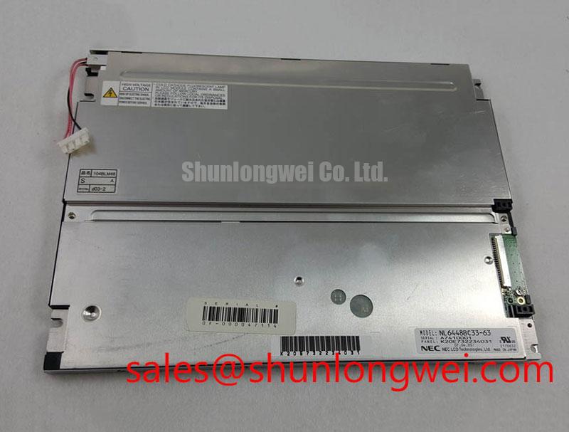
The neutral comparison point G121XN01-V1 can be reviewed when the repair team is assessing another same-class display option. This is an evaluation reference rather than a blanket substitution recommendation. The original machine controller, cable assembly, and bezel should determine final compatibility.
Thermal Expansion Clearance Sizing across Heavy Industrial Metal Enclosure Cutouts
Mechanical clearance should be checked before any electrical power is applied. A rigid machine-tool enclosure can load the panel unevenly when the display frame, gasket, and metal cutout are not aligned. During incoming inspection, place the panel against the enclosure without forcing the corners into position. Check that the bezel sits evenly, that mounting holes are concentric, and that the cable exit is not folded against a sharp edge.
The supplied product data does not define the outer bezel envelope, mounting-hole pattern, panel thickness, or an AUO-approved fastener torque for this model. Those dimensions must be taken from the original panel drawing or the equipment service documentation. General mechanical practice is to tighten fasteners progressively in a cross pattern, using only the torque approved for the enclosure and display assembly. The supplied value of 0.35 to 0.45 N·m should not be presented as an official B104SN01-V2 mounting limit without a source tied to the actual mechanical drawing.
Localized frame pressure can show as uneven luminance, corner shading, or dark-field mura after the panel is installed. Such an appearance may also result from cable stress, optical contamination, controller timing, or backlight variation, so the repair technician should compare the panel in a relaxed bench fixture with the panel installed in the enclosure. This comparison separates an installation effect from a display assembly condition.
Temperature changes also affect connector alignment and signal timing. TTL or LVDS terminology should not be assigned to this model without confirming the original interface documentation. When the host uses a differential display link, the engineer should review transmitter clock stability, data hold timing, cable routing, and signal quality across the equipment’s actual temperature window. An oscilloscope comparison with a known-good unit is more useful than inferring compatibility from the panel model number alone.
For industrial HMI integration, keep the cable bend radius, strain relief, and connector locking direction consistent with the original assembly. Designers should verify that the enclosure does not transfer vibration directly into the panel glass or cable termination. The relevant mechanical reference should also include the touchscreen or front cover if those parts are installed over the LCD.
Radiated Emissions and Grounding Considerations
Display noise near variable-frequency motor drives is best investigated as a system-level signal-integrity problem rather than as a confirmed characteristic of the LCD panel. Horizontal noise bands, intermittent pixel movement, or unstable image edges can be associated with cable routing, common-mode current, grounding geometry, controller timing, or power-converter noise.
The B104SN01-V2 baseline does not specify CISPR Class A or Class B compliance for a complete machine. A display module cannot independently claim the EMC performance of the finished HMI terminal. The equipment designer must evaluate the assembled enclosure, controller, cable shield termination, power supply, and motor-drive environment together.
As a Design Consideration, a shielded display cable should maintain a continuous shield path where the host and panel architecture supports it. Any 360-degree shield termination, backplate bonding, star-ground arrangement, or common-mode ferrite should be selected by the system EMC engineer after observing the actual interference path. Adding a ferrite without checking its effect on signal quality can alter edge behavior or create a new impedance discontinuity.
Separate noisy motor-drive conductors from display signal and backlight wiring. Route the display cable away from switching nodes and high-current return paths, then compare the screen with the drive disabled and enabled under the same display load. This controlled comparison can reveal whether the disturbance enters through radiation, conducted supply noise, or the signal reference connection.
When a TTL or LVDS transmitter is involved, check clock jitter and data hold behavior at the receiving connector, not only at the controller output. Cable length, connector transitions, grounding, and temperature can change the margin available to the receiver. The appropriate acceptance limits are determined by the controller and interface documentation. The reference article The Ultimate Guide to Industrial TFT-LCD Technology provides additional background for display selection and service evaluation.
Viewing-angle complaints should also be separated from electrical noise. The perceived image changes with observer position and contrast conditions; the general optical behavior is described in Viewing Angle Characteristics in LCDs. This is an optical reference, not a model-specific AUO specification.
Backlight Inverter and Ignition Debugging
Do not assume that B104SN01-V2 uses a CCFL backlight or a constant-current LED backlight from the model number alone. The confirmed baseline identifies a TFT-LCD active matrix color display module but does not establish the backlight technology, inverter requirement, lamp count, LED current, PWM input, or protection thresholds.
Before connecting a replacement, identify the original backlight harness and controller output from the equipment documentation. A CCFL inverter and an LED constant-current driver are different electrical subsystems. Applying a high-voltage inverter output to an LED assembly, or connecting an LED driver to a CCFL input, can damage the display system and create an unsafe test condition. The system integrator should verify the required supply voltage and backlight drive method from the original panel documentation.
For a confirmed CCFL configuration, cold ignition behavior should be measured with an appropriately rated high-voltage probe and an enclosure suitable for the test. The suggested 1500 to 1650 Vrms range supplied in the project brief is not an official B104SN01-V2 rating and should not be used as a repair limit for this model. A failed ignition event may involve the inverter, lamp wiring, connector insulation, control enable signal, or the lamp itself.
For a confirmed LED configuration, inspect the driver’s open-load response, short-circuit response, current regulation, and dimming control separately. The supplied 1000:1 PWM dimming figure and 50,000-hour half-brightness claim are not confirmed product specifications for this panel. They should not be printed as B104SN01-V2 performance values without a model-specific source.
Low-temperature response also requires system testing. LCD response time, backlight startup, cable flexibility, and controller behavior can change in a cold enclosure. If a machine operates below its normal laboratory temperature, evaluate image startup, gray transitions, brightness stability, and alarm outputs after the complete HMI assembly reaches the target condition. A heater strip should never be assumed to be part of this panel unless the equipment design explicitly includes one.
Incoming Benchtop Inspection: Panel Interconnect Integrity
Incoming inspection should begin with a full-screen image test, followed by a controlled dark-field check and a close inspection of the exposed flex and connector area. Display the primary red, green, blue, white, and black screens at a stable setting. Look for stationary bright points, dark points, vertical or horizontal line defects, uneven regions, and image changes when the cable is gently supported without applying pressure to the glass edge.
A 45-degree flashlight inspection can help separate surface contamination or external reflection from a display-line defect. In a darkened bench area, illuminate the front surface at an angle while the panel shows a black field. A mark that moves with the light source may be surface-related; a fixed line or region that remains with the image path requires further electrical and optical investigation. This method does not prove a COG or TAB failure by itself.
COG and TAB regions should be inspected without pressing the glass, driver edge, or bonded flex. Look for lifted edges, contamination, creasing, or evidence of connector misalignment. A line defect that changes when the cable is repositioned may indicate an interface or interconnect issue, while a stable defect across repeated power cycles may require comparison with the original panel and controller.
Backlight assessment should use a calibrated visual or optical method where available. Check center and edge uniformity, startup behavior, visible flicker, and brightness changes during the controller’s normal dimming command. LED lifetime curves, half-brightness hours, and PWM frequency limits are not confirmed in the supplied B104SN01-V2 baseline, so the driver documentation must define those values.
Bench Tip: Disconnect power before inserting or removing the display cable, protect the connector from ESD, and confirm that the flex is fully parallel before locking it.
The related display solution NL6448BC33-50 may be reviewed as a separate system-level reference when the repair team is comparing display and backlight architectures. It should not be treated as an automatic electrical substitute for B104SN01-V2. The final acceptance record should include the tested controller, cable assembly, mounting condition, image test patterns, backlight behavior, and any visible pixel or line observations.