
Content last revised on October 27, 2026
Assembly Integrity & Layout: Assessing CR6L-30/UL Mounting and Temperature
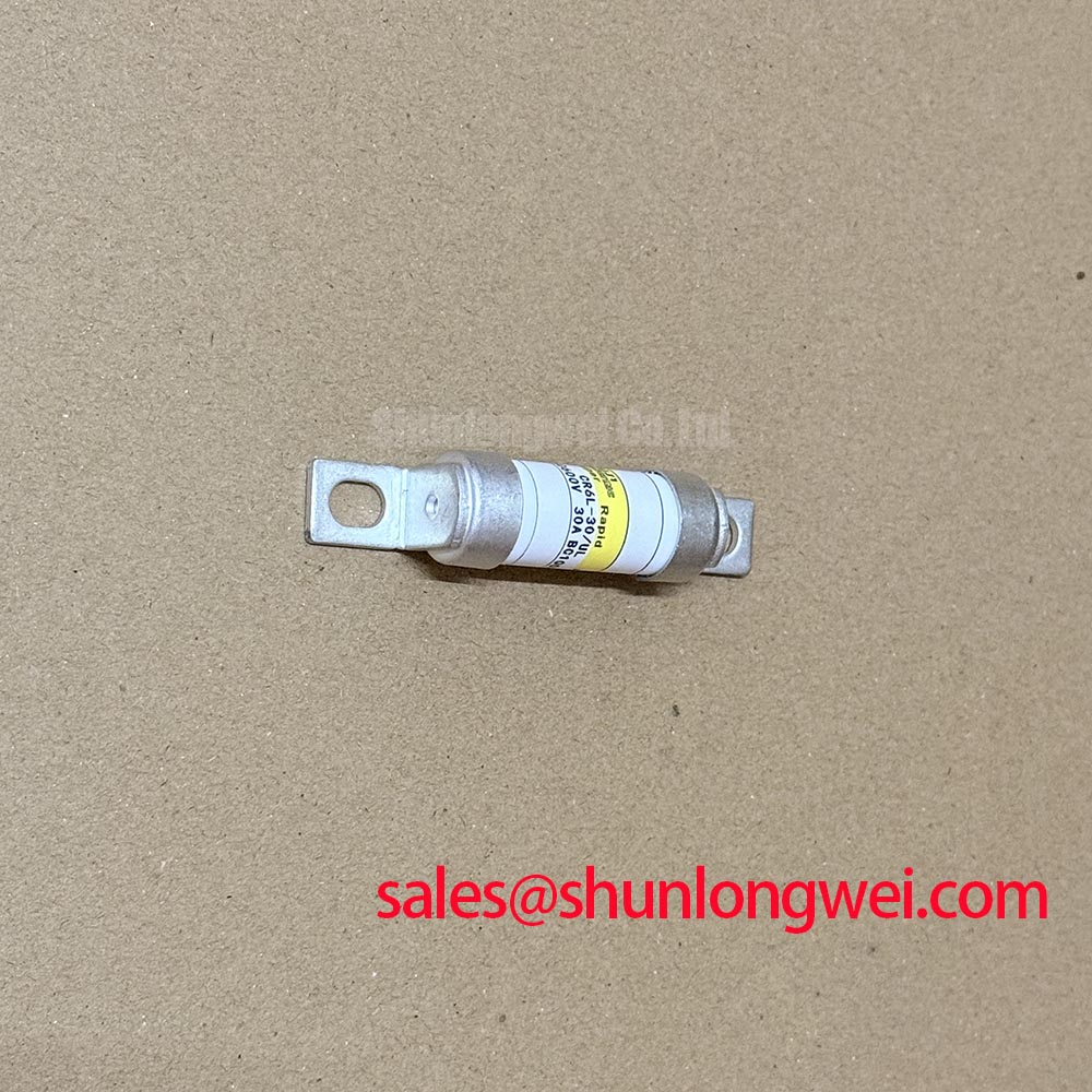
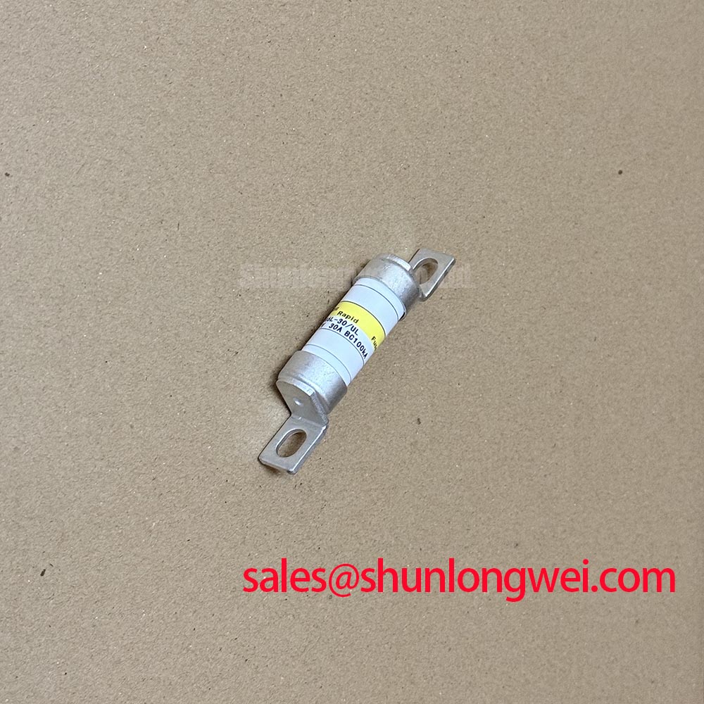
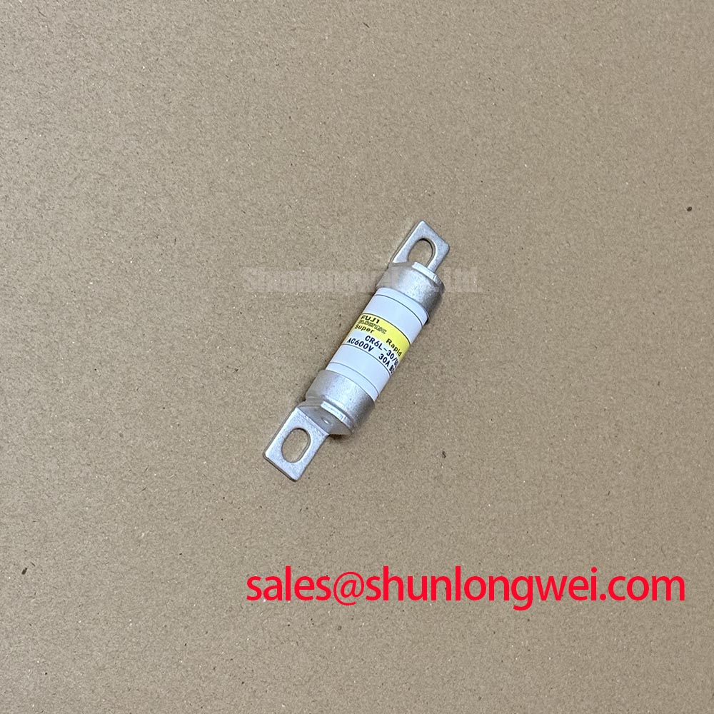
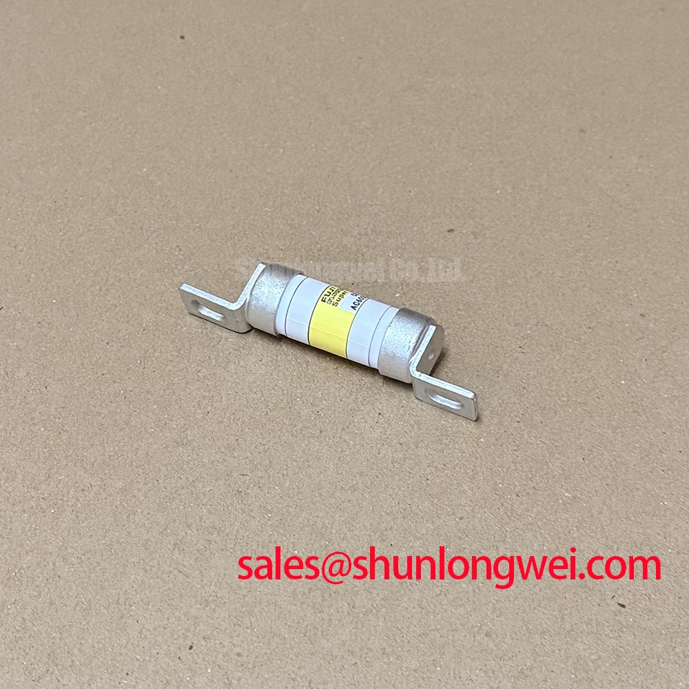
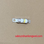
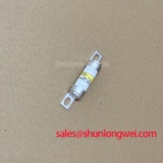
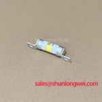
Isolate the supply, verify that stored energy has discharged, and inspect the fuse connections for discoloration or looseness before removing the CR6L-30/UL. This Fuji Electric High Speed Super Rapid Fuse belongs in the circuit-protection assessment, not the gate-driver or semiconductor-module replacement checklist.
For voltage, current, breaking capacity, dimensions, and clearing characteristics, consult the manufacturer’s datasheet. The model suffix alone must not be interpreted as a confirmed rating.
Inspect the fuse mounting interfaces and surrounding airflow before attributing elevated temperature to load current alone. As a Design Consideration, connection resistance, enclosure temperature, and adjacent heat sources should be evaluated together. Compare temperature observations under comparable operating conditions, recording load and measurement location so that subsequent maintenance checks remain meaningful.
A fuse has no collector-emitter saturation voltage or gate loop. Positive-temperature-coefficient current sharing and symmetrical gate wiring concern the protected semiconductor assembly, not the CR6L-30/UL itself. They cannot establish fuse suitability or justify parallel fuse arrangements. If the power stage contains parallel switching devices, assess their current distribution separately from the fuse selection and connection assessment.
For replacement planning, compare the complete designation, mounting geometry, approved connection method, and protection characteristics against the equipment bill of materials. The 1MBI300S-120 is a separate semiconductor-module reference, not an interchangeable fuse alternative. Keeping those component roles distinct prevents a mechanical fit check from becoming an unsupported electrical substitution.
Electrical Design: Coordinating CR6L-30/UL Fault Protection
Coordinate fuse clearing behavior with the protected circuit rather than treating a high-speed designation as proof that every semiconductor fault will be interrupted safely. As a Design Consideration, compare manufacturer-specified total-clearing I²t, peak let-through current, and breaking capacity with the equipment protection requirements under the applicable voltage and prospective fault current. I²t represents accumulated current-squared exposure over time; it does not independently establish semiconductor survival or enclosure containment.
For any proposed electric material-handling or forklift low-voltage traction application, designers should verify DC suitability, battery fault-current conditions, and coordination with contactors and electronic protection. An AC interruption rating must not be carried across to a DC circuit without explicit manufacturer support. Physical interchangeability alone does not resolve these questions.
Gate-driver sourcing and sinking capability, separate turn-on and turn-off resistors, and dead-time control belong to the switching stage. During a drive-board retrofit, engineers should assess those settings against switching waveforms and device limits; changing them does not alter the fuse rating. The system-level discussion in Mastering Power System Dynamics provides context for parasitic-inductance and snubber assessment without making those characteristics specifications of this fuse.
Connection Maintenance: Investigating Heat Around the CR6L-30/UL
Keep thermal-interface work on the semiconductor heatsink separate from the fuse mounting procedure. Copper-baseplate geometry, thermal-grease pump-out, and cross-pattern module tightening are not established CR6L-30/UL construction features. Do not apply a semiconductor mounting torque or thermal-interface thickness to its connections by analogy.
As an Engineering Recommendation, inspect the fuse holder or connection hardware for heat damage, contamination, and loss of contact pressure using the equipment service procedure. After reassembly, compare connection temperatures during a controlled operating check. A localized hot connection warrants investigation of the interface and loading rather than an immediate assumption that the fuse rating is incorrect.
Maintenance Note: Periodically inspect connection-temperature trends and airflow, and use the specified connection-tightening procedure rather than tightening hot terminals by feel.
Where the surrounding equipment includes an auxiliary converter, the buck–boost converter topology reference explains the conversion principle, not fuse qualification. Converter operating mode and energy paths should inform the equipment-level protection review, especially where current direction changes during operation.
Pre-Installation Checks: CR6L-30/UL Continuity and Fault Investigation
Check the isolated fuse for continuity using the approved service method; diode-threshold and gate-leakage tests do not characterize a fuse. An open reading establishes an interrupted conductive path, but does not identify the initiating fault. A continuity reading likewise cannot verify breaking capacity, clearing performance, or suitability for return to service.
Before installing a replacement, investigate the protected circuit for persistent shorts, damaged switching devices, and compromised connections. Semiconductor diode checks should be performed separately, with circuit isolation sufficient to avoid misleading parallel paths. Record the removed fuse designation, fault indications, and relevant operating conditions so that replacement approval rests on both component compatibility and fault resolution.
Release the assembly only after the specified fuse has been matched to the equipment requirements, connection hardware has been serviced, and the prescribed controlled restart checks have been completed.