

Content last revised on October 8, 2026
Preventing Spurious Faults: Saturable Reactor and Snubber Sizing Guidelines for DFA100BA160
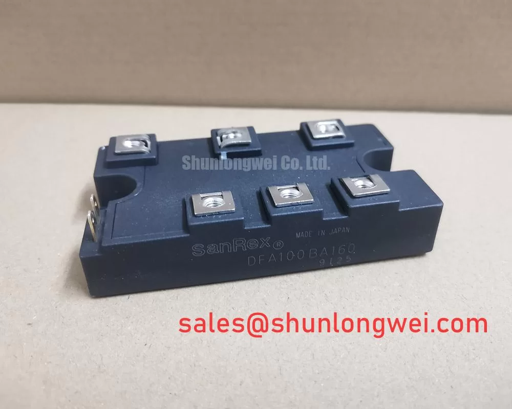
With the equipment isolated and its DC link discharged, compare the DFA100BA160 terminal markings with the original circuit drawing before taking cold-state diode measurements. Record the meter polarity, terminal pair, and module temperature so that subsequent comparisons use the same conditions. This SanRex (Sansha Electric) bridge rectifier module must be evaluated as a rectification component, not as a gate-controlled switching module.
The product’s official specification identifies a 1600 V voltage rating, a 100 A current rating, and a SanRex Power Module package. These headline ratings establish the initial selection boundary; they do not establish an unrestricted operating current at every case temperature or a permissible AC input voltage. Check the manufacturer’s rating definitions and associated conditions before approving an equipment replacement.
| Parameter | Official Specification | Integration check |
|---|---|---|
| Model | DFA100BA160 | Match the complete designation to the equipment documentation. |
| Manufacturer | SanRex (Sansha Electric) | Use the corresponding manufacturer terminal drawing. |
| Rated voltage | 1600 V | Verify the voltage definition and transient operating boundary. |
| Rated current | 100 A | Verify temperature, waveform, and cooling conditions. |
| Package | SanRex Power Module | Confirm mounting geometry and terminal clearance. |
Design Consideration: Assess an existing RC snubber or series reactor against measured commutation transients and the equipment schematic. A diode bridge does not have thyristor-style spurious gate turn-on. Reactor and snubber requirements therefore belong to the complete rectifier circuit, rather than an assumed trigger-protection requirement of this module. Resistor dissipation, capacitor pulse capability, and reactor behavior require system-level verification.
For comparative selection, the FRS200CA100 is a separate product to investigate, not an established substitute. Compare topology, polarity, terminal positions, thermal conditions, and mounting dimensions before considering interchangeability.
Preventing Spurious Faults: Surge Energy Dissipation and Clamping Voltage Guidelines for DFA100BA160
Trace the AC input protection, rectifier connections, and DC-link charging path before selecting surge suppression. Design Consideration: A protection device should limit the transient reaching the rectifier while remaining compatible with normal supply conditions. Its clamping behavior depends on surge current and wiring impedance; the module’s voltage rating alone cannot determine a suitable MOV or snubber.
Surge immunity evaluation should reference the applicable equipment requirements and IEC 61000-4-5, rather than treating that standard as a component certification. Confirm the required test configuration with the system engineer. No equipment-level EMC compliance follows from installing this bridge rectifier.
Fuse coordination also requires the manufacturer’s surge-current and I²t limits, together with the fuse’s clearing characteristics. Those values are not established by the headline ratings above. Avoid approving a fuse from continuous current alone. Where an equipment drawing includes a separate auxiliary rectification stage, SKD 25/14 documentation can support that stage’s assessment without implying compatibility with DFA100BA160.
Preventing Spurious Faults: Gate Trigger Current and Temperature Dependence Guidelines for DFA100BA160
The gate-trigger question has a direct answer: this bridge rectifier is not specified here as a thyristor module. Gate trigger current, gate trigger voltage, holding current, and strong-trigger pulse trains are therefore not acceptance parameters for DFA100BA160. Do not transfer gate-drive requirements from a controlled rectifier or an adjacent inverter into its incoming inspection procedure.
💡 Bench Tip: Disconnect parallel circuit paths before comparing cold-state diode readings, because connected snubbers and other components can obscure the module’s own response.
Engineering Recommendation: Follow the terminal schematic and compare forward and reverse measurements with a documented reference using the same instrument. A diode-mode reading is a screening observation, not proof of rated-current performance or reverse-blocking capability. Unexpected readings warrant connection checks and controlled follow-up testing, rather than a single-cause diagnosis.
For a medium-frequency induction melting or hardening furnace, engineers should first establish whether the proposed location is the input rectifier stage. Inverter gate bias, bootstrap circuitry, and switching-diode recovery require separate component documentation.
Preventing Spurious Faults: Thermal Interface Material Spreading Guidelines for DFA100BA160
Inspect the mounting surface, mating heatsink, and interface coverage before installation. Design Consideration: Uneven contact or module distortion can impair heat transfer, so use the manufacturer’s mounting sequence, specified torque, and approved interface procedure. Do not infer baseplate material, thermal resistance, or allowable interface thickness from the package name.
Keep thermal assessment separate from electrical insulation testing. Confirm the manufacturer’s insulation-test voltage, test points, duration, and equipment requirements before applying a withstand test; the 1600 V semiconductor rating is not an insulation-test instruction.
The discussion in Unlocking Efficiency in Industrial Drives concerns another semiconductor technology and cannot establish this rectifier’s losses or lifetime. Likewise, MTBF and reliability engineering distinguish reliability estimates from guaranteed service life. An equipment HMI check using viewing-angle characteristics addresses display readability, not rectifier temperature verification. Validate the installed module through the equipment’s defined electrical and thermal acceptance procedure.