
Content last revised on September 20, 2026
DFM600FXM18-A000 Thermal-Electrical Optimization: Saturable Reactor and Snubber Sizing to Practical Tuning
Before evaluating an RC snubber or a series saturable reactor, establish whether those parts are present in the original circuit and document their electrical connections. A snubber network cannot be selected safely from the module current rating alone. Its behavior depends on the measured switching waveform, DC-link arrangement, stray inductance, load path, protection coordination, and gate-drive behavior. This is a Design Consideration: minimize the commutation-loop inductance where inductive overshoot could challenge the verified system voltage margin, then confirm the result with measured waveforms under controlled switching conditions.
The 600.0A rating is an official identification point, not a substitute for time-current coordination. If the equipment documentation provides a semiconductor fuse coordination table and I²t data, use those original values to confirm that the protective device is appropriate for the installed topology. Do not infer an I²t capability, surge rating, or fault-clearing behavior for DFM600FXM18-A000 from its package description. A fuse chosen for a related assembly may have different requirements because conductor geometry, fault source impedance, and commanded operating states change the available fault energy.
For a repair inspection, examine the snubber capacitor, resistor, reactor, busbar supports, and terminal joints for heat discoloration, loose hardware, cracked insulation, or signs of movement. A waveform with ringing or unexpected turn-on behavior can arise from several sources, including altered wiring geometry, degraded passive parts, an incorrect gate-drive reference, or measurement technique. It should be investigated against a known-good phase or an approved commissioning trace rather than attributed to one component without evidence.
In SVC and thyristor-switched capacitor equipment, passive commutation components are often evaluated as part of the larger switching and harmonic-control network. The MBM200H45E2-H can be reviewed as a separate associated device where the documented system includes a front-end rectification or complementary power stage. Electrical compatibility must be established from the equipment schematic and verified ratings, not from a name-based association.
Transient Dynamics & Electrical Design: Ensuring Uniform Heatsink Contact Pressure on DFM600FXM18-A000
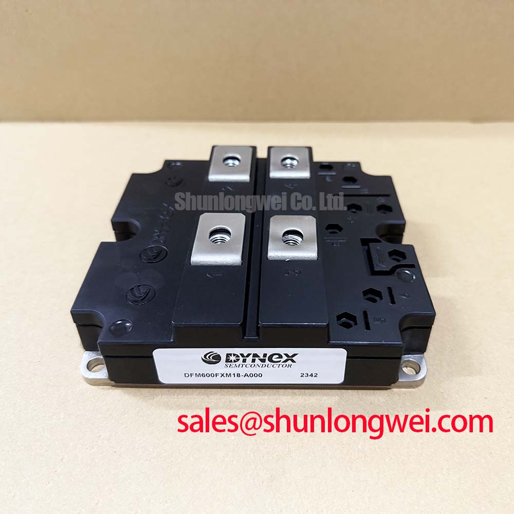
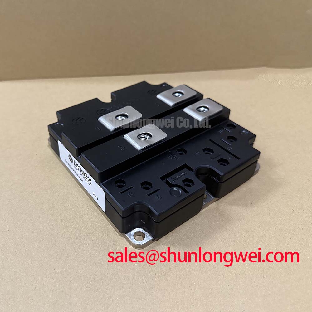
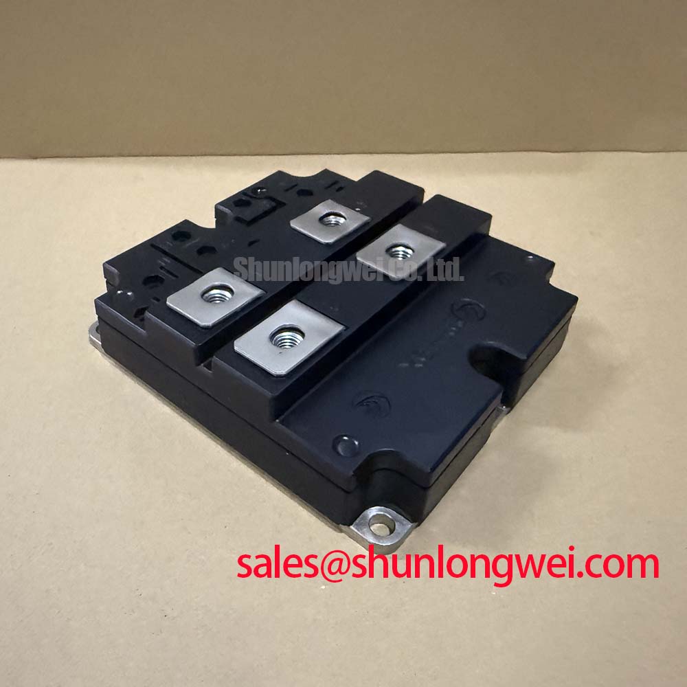
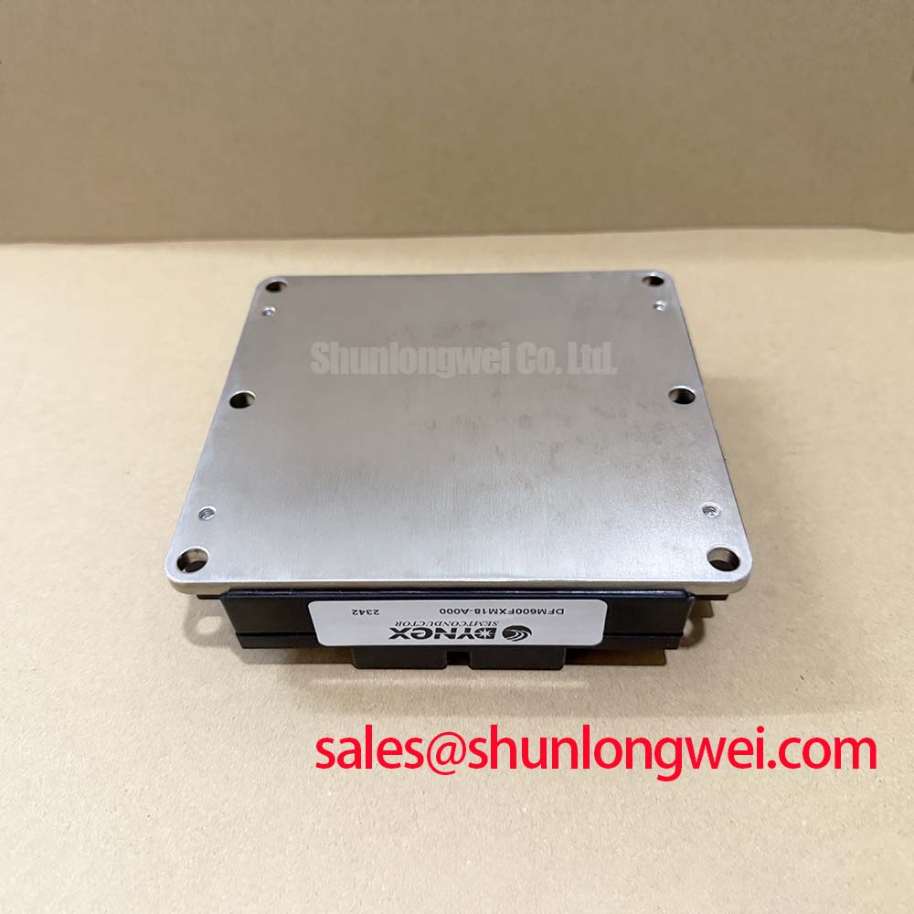
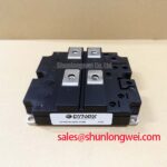
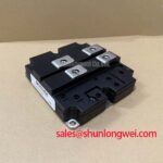
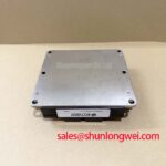
Remove the module only after the energy-storage sections have been discharged and absence of voltage has been verified by the site procedure. Record the terminal orientation and the heatsink contact pattern before disturbing the assembly. The DFM600FXM18-A000 is supplied in a High-Power Traction Module housing, but no mounting torque, baseplate flatness, thermal resistance, or interface-material thickness is established by the supplied official parameter set. These values must come from the original Dynex documentation and the equipment manufacturer’s mechanical drawing.
During bench examination, inspect the mounting face and heatsink for trapped debris, raised burrs, corrosion, or damage that would prevent full contact. Apply the thermal-interface material according to the approved equipment process and tighten mounting hardware in the prescribed sequence and torque. This is an Engineering Recommendation, not a module-specific factory torque claim: uniform clamping is needed to avoid distorting the housing while promoting consistent thermal transfer across the intended contact area.
Bench Tip: Keep the module and test fixture at the same cold-state condition when comparing diode-mode readings, and use ESD-controlled handling before touching gate or control terminals.
Rth(j-c) is often necessary for a complete thermal review, but it is not provided in the stated official data. Do not calculate junction temperature, heatsink capacity, or continuous overload capability without the relevant manufacturer curves and the measured system duty cycle. A thermal anomaly may be associated with uneven mounting pressure, insufficient cooling flow, altered load duty, a drive issue, or a damaged passive network. Thermal imaging and controlled electrical measurements are more defensible than a visual conclusion alone.
Where forced-air cooling is used, airflow paths and local recirculation should be assessed at enclosure level. Computational fluid dynamics is a useful industry reference point for understanding why apparent fan operation does not always demonstrate effective heatsink cooling. Any airflow model or temperature limit remains a system-level analysis and must be validated against the installed mechanical design.
DFM600FXM18-A000 Operational Boundaries: Evaluating AC-to-DC Transfer Characteristics across V Limits
Verify the actual circuit family before applying AC-to-DC transfer analysis to this module. The supplied product information identifies DFM600FXM18-A000 as an IGBT module with a 600.0A official current rating; it does not establish firing-angle behavior, gate-trigger current, gate-trigger voltage, holding current, or thyristor transfer curves. Those are not interchangeable characteristics. A phase-controlled rectifier or thyristor-switched capacitor branch must be evaluated using the specifications of the installed thyristor devices and the original control diagram.
For equipment that contains both IGBT-based and thyristor-based functions, record which controller output drives which semiconductor location. In a controlled AC-to-DC stage, firing angle affects average conversion behavior, displacement factor, reactive demand, and harmonic content. The resulting limits depend on source impedance, transformer arrangement, filters, capacitor banks, load behavior, and the protection sequence. This is a Design Consideration: evaluate the applicable firing range only with the documented power-stage topology, while confirming line current and voltage behavior with suitably rated instruments.
Do not present an alpha range, a power-factor target, or a harmonic result as a property of DFM600FXM18-A000 when the official input information does not state it. Engineers assessing a grid-tied static var compensator and thyristor-switched capacitor system should compare the installed controller’s command timing with the original commissioning record, protection thresholds, and permitted grid operating conditions. A deviation can require investigation of sensing circuits, synchronization, current feedback, control logic, external passive components, or the power devices themselves.
Technical papers in IEEE Transactions on Power Electronics provide useful peer-reviewed context for converter switching, gate-drive interactions, and grid-connected power-electronic behavior. They do not replace the manufacturer data required to define this module’s exact electrical limits.
Field Diagnostics & Commissioning: Preventing Localized Gate Hotspot Burnout in DFM600FXM18-A000 Topologies
Start commissioning checks with the equipment de-energized. Confirm terminal-to-terminal continuity expectations against the official pinout, inspect control harnesses for damaged insulation and connector strain, and compare cold-state semiconductor readings with an approved reference unit or known-good phase where available. A multimeter diode-mode result is a screening observation only. It can identify an obvious abnormal conduction path, but it cannot establish switching health, dynamic current sharing, insulation performance, or safe operation at rated current.
The available official data does not specify DFM600FXM18-A000 gate-pulse rise time, gate-current slope, back-porch holding current, multi-pulse firing requirements, IGT, or VGT. These values must not be assumed from a thyristor controller, a different Dynex module, or a general IGBT drive practice. If the installed topology uses gate pulses or negative gate bias, the drive waveform should be examined at the module terminals with an appropriate isolated measurement arrangement and compared with the equipment documentation.
Gate-loop inductance, return-path routing, control supply stability, common-reference behavior, and protection response can all affect observed switching. An unexpected waveform may indicate impedance mismatch or a drive-path problem; verify it with an oscilloscope against a known-good signal path before replacing additional parts. For practical context when evaluating an off-state gate-drive approach, see Evolution of Negative Off-Bias Gate Drive Circuits. That resource supports circuit-level review and does not define a required drive voltage for this specific module.
When the original unit cannot be retained, the DIM800DCM17-A may be reviewed as a separate candidate during a documented engineering compatibility assessment. Confirm its voltage class, current behavior, mechanical envelope, terminal map, thermal interface, gate-drive requirements, protection coordination, and system qualification before any substitution decision. No replacement should be approved solely because two modules appear similar in current class or physical format.