

Content last revised on October 25, 2026
Field Diagnostics & Commissioning: Insulation Barrier Checks in DP15F1200T0101910 Topologies
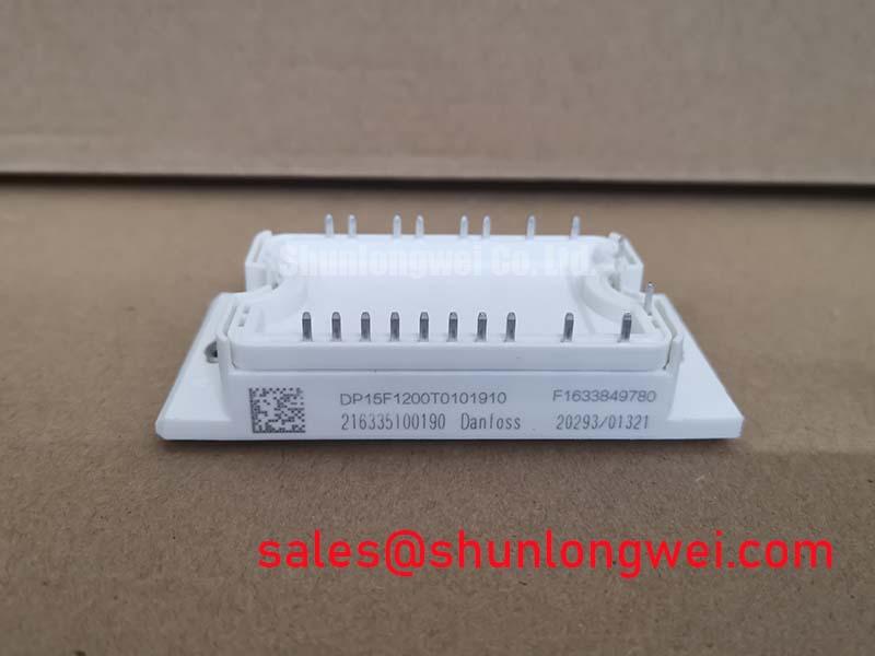
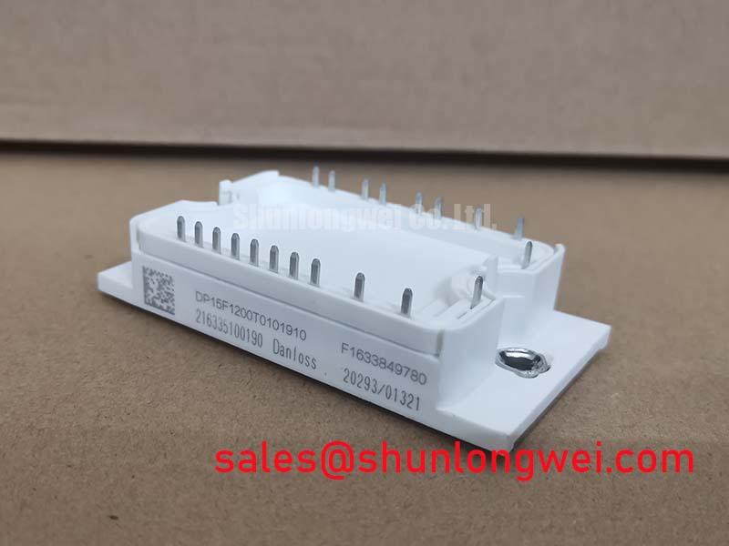
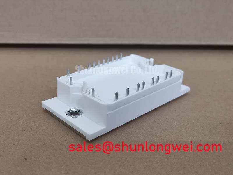
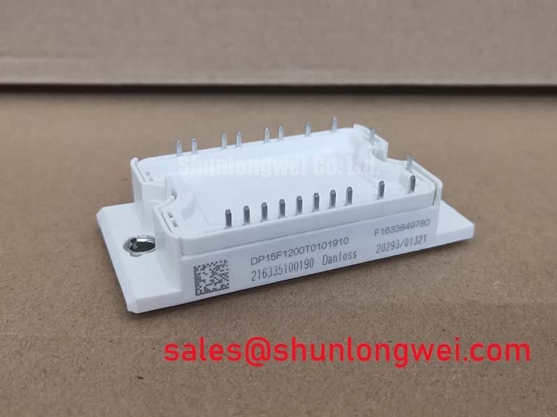
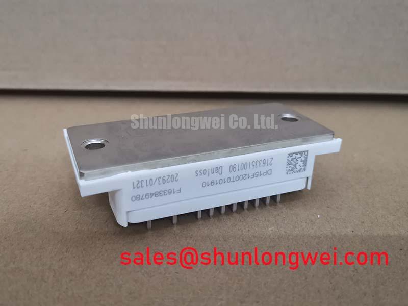
With the drive isolated and its DC link discharged, inspect the module terminals and mounting surface before taking cold checks against the equipment’s service procedure. The Danfoss DP15F1200T0101910 is specified as a 1200 V, 15 A IGBT module from Danfoss Silicon Power. These are product ratings, not a substitute for checking the installed circuit’s operating conditions and the original module documentation.
Record the drive’s fault code, confirm the DC link is safely discharged, and inspect for loose connections, contamination, cracked housing, or signs of overheating. A multimeter check can help identify an obvious short between power terminals, but readings depend on the circuit and meter; compare with the manufacturer’s test procedure rather than treating a single reading as a pass or fail. Before fitting a replacement, check the complete part number, terminal arrangement, mounting interface, and application requirements.
Begin commissioning by confirming the module’s place in the power stage and tracing the isolation boundaries in the equipment schematic. The specified 1200 V rating does not, on its own, establish a reinforced-insulation rating, a dielectric test voltage, or common-mode transient immunity. Do not assign the module unsupported isolation or CMTI values; verify those characteristics from applicable manufacturer documentation for the exact assembly and system.
For field checks, isolate control wiring from power wiring as the service procedure permits, then inspect board slots, insulating barriers, cable routing, and contamination paths. Creepage and clearance requirements depend on working voltage, pollution conditions, material group, and applicable product standards. The system designer should assess these conditions against the equipment’s safety requirements rather than applying a generic distance as a module specification.
When a drive reports intermittent switching or ground-related faults, inspect connector seating and the physical separation of gate-drive and power conductors. Check signal behavior using suitable isolated measurement equipment and compare it with a known-good channel or the service documentation. The general principles behind package and system-level power-module arrangements are outlined in Power Module Architecture & Topologies.
Preventing Spurious Faults: Floating Gate-Bias Supply Checks for DP15F1200T0101910
Verify the gate-driver supply rails and enable sequence at the driver interface before reconnecting the high-voltage DC link. A negative turn-off bias, UVLO threshold, and startup sequence are driver and system design choices; they are not established by the module’s 1200 V and 15 A ratings. Set these conditions from the gate-drive design and the applicable device documentation, then confirm that undervoltage interlocks prevent switching when the supply is outside its valid range.
Trace each gate and emitter connection from the module terminals to the driver board, checking polarity and continuity against the equipment schematic. Keep the gate loop compact and route it to limit coupling from high-current switching paths. Inspect busbar joints and fasteners for looseness or mechanical movement, using the equipment maker’s assembly procedure and specified hardware. Field alert: Never reconnect or tighten power connections while the DC link is energized.
For a replacement assessment, compare the mechanical interface, terminal map, thermal path, and electrical ratings rather than relying on a similar-looking package. BSM35GD120DN2 is another module listing that may be reviewed during sourcing, but its presence here does not establish interchangeability; confirm the circuit and manufacturer documentation before selecting any alternate. In a broader converter assembly, the FP100R12KT4-B11 can be examined as a separate power-stage component, not as an assumed companion or replacement for this model.
DP15F1200T0101910 Switching Behavior: Gate Bias and Miller-Control Design Considerations
When evaluating unintended turn-on during fast switching, examine the complete gate-drive loop, driver return path, and switching-node waveform. Parasitic coupling can disturb the gate voltage, while long or poorly routed conductors can contribute to ringing. Minimize loop area and keep gate-drive routing separated from high-current paths where the board layout allows; validate the result under the system’s actual switching conditions.
Negative gate bias and active Miller clamping are possible design approaches, not guaranteed features or prescribed settings for the DP15F1200T0101910. The appropriate method depends on the driver, switching conditions, and device limits. Review gate-emitter voltage at the module terminals with a measurement setup suited to the transient environment, and investigate ringing, overshoot, or cross-conduction indications before returning the equipment to service.
When assessing the module for a light industrial automation drive or multi-joint robotic actuator, check its rated current and voltage alongside the drive topology, switching profile, cooling arrangement, and protection coordination. Surge-current capability, junction-temperature limits, gate-charge values, and fuse I²t coordination require applicable device and system data; they cannot be inferred from the 15 A rating alone. For topology context, consult Resonant Topologies in Home Appliances as a separate technical resource, while confirming that the topology discussed matches the equipment under repair.