Shunlongwei Co. ltd.
IGBT Module / LCD Display Distributor
Customer Service
+86-755-8273 2562
IGBT Module / LCD Display Distributor
“ECM refers to electret condenser microphone, which is different from MEMS silicon microphone, and its internal structure is shown in Figure 1. There is a diaphragm capacitor charged with a certain charge inside the MIC, and one of the capacitor plates is connected to the FET. Since the input impedance of the base of the FET is very high, it can be considered that the charge of the capacitor will not disappear.The diaphragm vibrates with the external sound pressure, causing the distance between the two plates of the capacitor to change, resulting in a change in the capacitance. It can be known from the capacitance formula that when the charge is constant, when the capacitance value changes, the voltage will also occur. change, i.e. a change in the GS voltage of the FET causes a change in the DS current, and a change in the current causes the external bias resistor
“
1. Principle of ECM
ECM refers to electret condenser microphone, which is different from MEMS silicon microphone, and its internal structure is shown in Figure 1. There is a diaphragm capacitor charged with a certain charge inside the MIC, and one of the capacitor plates is connected to the FET. Since the input impedance of the base of the FET is very high, it can be considered that the charge of the capacitor will not disappear. The diaphragm vibrates with the external sound pressure, causing the distance between the two plates of the capacitor to change, resulting in a change in the capacitance. It can be known from the capacitance formula that when the charge is constant, when the capacitance value changes, the voltage will also occur. Change, that is, the change of the GS voltage of the FET leads to the change of the DS current, and the change of the current causes the voltage on the external bias resistor to change, so that the DS voltage of the MIC output terminal changes, the voltage change and the voltage change of the bias resistor. equal.
The above working principle in Figure 1 is actually the amplification of triodes (or MOSFETs). In actual work, most of the triodes (or MOSFETs) we use are mostly switching. “, I briefly described the static operating point setting method of the triode amplification area. Its essence is the same as the working principle of the FET inside the MIC, so that the FET works in the saturation area (corresponding to the linear amplification area of the triode).
2. ECM parameter specifications
According to the explanation of the above reference article, in order to maximize the dynamic range of the MIC output voltage, a suitable bias resistor is required to set the positive + output voltage to half of Vs. According to the electrical parameters in the MIC specification (Figure 2), the quiescent current is 500uA, so RL=(Vs-V+)/Idss=(2-1)V/500uA=2K, and 2.2K is actually selected, which is not much different. . This is also the working condition recommended by most MICs: 2V bias voltage, 2.2K bias resistor. Under this condition, the static voltage Vbias=2-2.2K*500uA=0.9V across the MIC can be calculated.
Figure 2 After setting the bias resistor, we need to determine the AC voltage output by the MIC, because the really useful sound information is contained in the AC voltage signal. According to the AC equivalent model of the analog MOSFET, the AC equivalent Circuit of the MIC is shown in Figure 3. Since the rgs of the FET is very large, the charge on the diaphragm capacitor will basically not be discharged and disappear; because rd is relatively large relative to RL, rd can be ignored after parallel connection, so the AC output voltage of the MIC is V=gmVgs*RL. To obtain a larger effective AC output signal, the bias resistor RL can be increased. Increasing the bias resistor will make the dynamic range smaller, but since the maximum peak-to-peak output voltage of the MIC will not be very large (see below for details), unless the bias resistor is set too large and unreasonable, the general situation will not cause the output waveform to be distorted.
Figure 3 In addition, it can be seen from the electrical parameters that the sensitivity of the MIC is -38dB, and the maximum input sound pressure level is 110dB SPL. From these two parameters we can get the maximum effective voltage value of the MIC output. First, the sensitivity of the MIC is defined as: the ratio of the output voltage to the input sound pressure under the excitation of unit sound pressure, that is, when the sound pressure is given to the MIC 1Pa (94dB SPL sound pressure level), the microphone output voltage (dBV),
 ,
,
The sensitivity of the available MIC![]() . The sound pressure level is represented by the symbol SPL, which is defined as the ratio of the effective value of the sound pressure to be measured P(e) to the reference sound pressure P(ref),
. The sound pressure level is represented by the symbol SPL, which is defined as the ratio of the effective value of the sound pressure to be measured P(e) to the reference sound pressure P(ref),
 Pr=2*10E-5Pa,
The maximum sound pressure of the MIC can be obtained
![]()
Therefore, the maximum output effective voltage of the MIC is 6.32*12.59mV=79.6mV (rms), and the corresponding maximum peak value is 79.6*1.414=112mV. Therefore, the voltage across the MIC is: Vbias=0.9V; Vac=±0.112V. It can be seen from this that the effective voltage is relatively small, so it is feasible to sacrifice a part of the dynamic range by increasing the bias resistance above to obtain a larger output voltage.
3. ECM circuit parameter design
The typical application circuit of ECM is differential connection, as shown in Figure 4, and its AC equivalent circuit is shown in the figure. Resistors R3, R6 and capacitor C3 form RC low-pass filtering to filter the power supply MICBIAS. Resistors R4 and R5 are the bias resistors of the MIC. According to the AC equivalent circuit (Figure 5), R4+R5=RL=2.2K, so R4=R5=1.1K. Assuming Vbias=2.4V, in order to make the voltage at the red circle in the figure equal to the working voltage 2V recommended by the MIC, the voltage drop on the resistor R (=R3+R6)=2.4-2=0.4V, then R=0.4/500uA =800R, therefore, R3=R6=400R, take the common value of 390R. This is a theoretical calculation value, but in many cases, in order to obtain a larger effective AC output voltage, a larger bias resistor will be selected, which can be weighed according to the actual situation. Assuming that the cutoff frequency of the RC low-pass filter composed of resistors R3, R6 and capacitor C3 is 10Hz, then 1/(2πRC)=10, C3=C=20uF, and the common value is 22uF. C3 can be equivalent to two capacitors connected to the ground respectively, that is, two capacitors are connected in series, and the value of each capacitor is 2C=44uF (the capacitors are connected in series, and the capacitance value is reduced by half).
C6 is used to filter out differential mode interference, generally 220pF, C4 and C5 filter out common mode interference, generally 33pF. The resistors R1 and R2, the input impedance Rc of the Codec chip pins, and the DC blocking capacitors C1 and C2 form a high-pass filter. Under normal circumstances, the input impedance of the chip pins is relatively large, and R1 and R2 can be ignored, so many designs can not use the resistors R1 and R2.
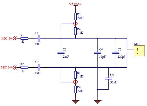
Figure 4
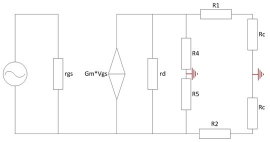
Figure 5 ECM has another differential connection method, as shown in Figure 6, the parameter calculation method is the same. The AC output is the same as the previous connection, but this connection has the advantage that the static voltage input from the MIC to the Codec will not be affected by the Vbias voltage fluctuation. The static voltage is the voltage drop of the resistor R4, and the MIC The quiescent current can be considered basically unchanged, so the quiescent voltage drop of R4 is also unchanged. In the previous connection, when Vbias changes, the static voltage at both ends of the MIC will change due to the voltage drop of the external resistor, which makes Codec mistakenly believe that there is an AC output from the MIC, resulting in noise.
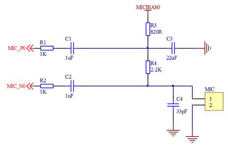
Figure 6 can also be seen from the above analysis, no matter what kind of differential connection method, it is not really differential, because the common mode voltage of the differential signal is the same, and the above differential connection method, the common mode voltage of P and N is different. Therefore, the fluctuation of Vbias will make the common mode voltage change into differential mode voltage, forming noise. In addition to the differential connection method of the MIC, a method called pseudo-differential connection can also be found on the network, as shown in Figure 7. The difference is that one end of the MIC is grounded, and one signal in the differential pair is connected to the ground with an external resistor, which needs to match the output impedance of the MIC. I haven’t used this circuit, so I don’t know the actual effect, and I won’t introduce it too much.
In addition to the differential connection method in Figure 7MIC, there is also a common single-ended connection method, which is the principle part described at the beginning of the article, and will not be repeated.
4. Notes on ECM circuit layout
Taking the actual application of differential connection circuit as an example (Figure 8), except C156, C157 and C153 should be placed close to the chip pins, other resistance and capacitance should be placed close to the MIC position. It will be mentioned in some materials that the resistance and capacitance related to MICBIAS should be placed close to the chip, but I personally think that this part of the resistance and capacitance should also be placed close to the MIC, because the MICBIAS voltage is used to power the MIC, and at the same time the MICBIAS pin position of the chip A filter capacitor C153 is also placed. Differential connection method should pay attention to the wiring according to the differential rules. In addition, a point that needs to be noted is that the ground of the audio part and the system ground are best separated to avoid interference.
Figure 8 This is the end of this article. After all, I am not an audio professional, and I only made a brief summary of past projects. If there are any mistakes or deficiencies in it, please enlighten me if you see it.
The Links: LQ123K1LG03 7MBP150RA060-05