Content last revised on October 19, 2026
Fuji Electric ETK81-050 500 V 80 A Diode/Thyristor Module for SVC Systems
Isolate the converter, then check the ETK81-050 terminals for abnormal cold-state impedance, loose connections, and visible case or baseplate damage before energizing a grid-tied compensation cabinet. This first inspection helps separate a semiconductor fault from a gate firing, fuse, wiring, or heatsink problem.
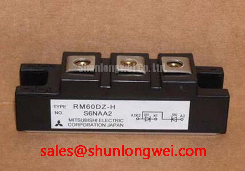
The Fuji Electric ETK81-050 combines diode and thyristor functions in one power module. Its official listed ratings include a 500 V repetitive peak reverse voltage for the diode section and a 500 V repetitive peak off-state voltage for the thyristor section. The diode section is rated at 80 A average forward current, while the thyristor section carries a 50 A average on-state current. These values support initial compatibility screening for controlled rectifier and thyristor-switched capacitor assemblies, subject to the complete circuit duty and cooling design.
- Manufacturer: Fuji Electric
- Module type: Diode/thyristor module
- VRRM: 500 V, official specification
- ID: 80 A average forward current, official specification
- IFSM: 850 A peak surge forward current, official specification
- VDRM: 500 V, official specification
- IT(AV): 50 A average on-state current, official specification
- Tj: −40 to +125 °C, official specification
- Rth(j-c): 0.25 °C/W for diode and 0.40 °C/W for thyristor, official specification
- Visol: 2500 V for one minute, official specification
Assembly Integrity and Pulse Firing Layout for ETK81-050
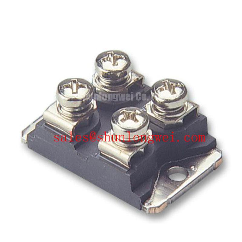
Gate firing reliability depends on a clean terminal layout, controlled pulse timing, and a low-noise return path. During service work, identify the main power terminals and gate connections from the original equipment drawing rather than assuming a universal pin sequence. A wrong gate or cathode connection can leave the power stage apparently intact while preventing controlled conduction.
For a thyristor-switched capacitor or SVC branch, the firing circuit should provide a repeatable gate pulse with sufficient rise performance and a defined holding interval. A pulse-train arrangement can be evaluated when the control board must maintain reliable triggering under electrical noise, but the final timing remains a system design decision. Check the gate waveform at the module terminals with the cabinet wiring installed, because cable inductance, isolation circuitry, and return routing can alter the pulse seen by the device.
Use the specified IFSM of 850 A as a surge-rating reference, not as a continuous operating target. Fuse selection, branch impedance, firing angle, and capacitor discharge behavior must be coordinated together. The external protection study should use the applicable semiconductor fuse clearing data and the device manufacturer’s permissible surge information. For related hardware evaluation, engineers can compare the construction and ratings of ETK85-060 without treating it as an automatic substitute for the ETK81-050.
🔧 Field Alert: Confirm the original equipment tightening specification and use an even, thin thermal interface layer before applying power; excessive or uneven clamping can distort the module base and degrade thermal contact.
Thermal Interface and Protection Coordination
The two listed junction-to-case thermal resistance values require separate attention during thermal assessment: 0.25 °C/W for the diode and 0.40 °C/W for the thyristor. Inspect the heatsink contact surface for burrs, contamination, and local rocking before installation. The mounting method should distribute pressure across the baseplate rather than concentrate force near a single fastener.
After assembly, check that the module sits flat and that the thermal compound has spread consistently across the intended contact area. Do not use the visible compound pattern as a substitute for temperature testing. Under operating load, compare temperatures between the diode and thyristor conduction paths while considering switching frequency, conduction angle, airflow, and heatsink conditions.
The 2500 V isolation voltage is an official one-minute isolation specification between the terminals and baseplate. It does not establish the complete cabinet clearance or creepage design. The enclosure, busbar geometry, contamination level, and installation environment determine the required insulation coordination. Surge suppression may be considered at the system level; the operating principles of TVS diodes for surge protection are relevant when selecting external protective networks.
In the wider power path, a rectifier stage may operate alongside a controlled switching branch. The 2DI240A-055 can be reviewed as a related upstream or complementary module, while voltage, current sharing, fusing, and thermal behavior must be checked for the actual topology.
Bench Waveform Tuning and Fuse Clearing Assessment
Bench testing should begin with the control circuit disconnected from the live power path and continue through staged voltage and current checks. Observe the thyristor gate pulse at the module terminals, then verify that the intended conduction interval matches the controller command. Unexpected partial conduction can reflect timing, gate-return routing, isolation behavior, or a damaged semiconductor path rather than one universal failure cause.
Fuse coordination requires the fuse total clearing I²t to be evaluated against the diode and thyristor surge withstand data for the actual fault loop. The calculation must include prospective fault current, source impedance, capacitor energy, fuse operating characteristics, and wiring inductance. A fuse that interrupts quickly in one branch may not provide the same protection in another topology. Record the clearing behavior during controlled protection testing rather than relying only on the fuse’s nominal current label.
For high-voltage SVC service, inspect the gate-drive isolation path for common-mode transient disturbance and keep high-current commutation loops physically separated from sensitive control returns. The external reference on thyristor and SCR dynamics provides useful background for interpreting latching and turn-off behavior. Practical gate-drive and switching-layout checks can also be organized with the Precision Gate Drive Design reference.
Before returning the cabinet to service, verify terminal polarity, gate identification, heatsink seating, fuse coordination, isolation test conditions, and waveform behavior under the intended firing sequence. The specified −40 to +125 °C junction-temperature range remains an official device boundary; actual cabinet operation must be assessed from measured semiconductor temperature, cooling performance, and duty profile.