

Content last revised on October 23, 2026
Transient Dynamics & Electrical Design: Mitigating DC Ripple Currents in ETK85-058 Rectifier Applications
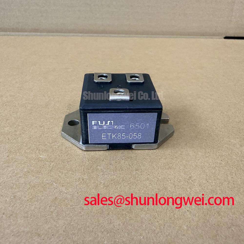
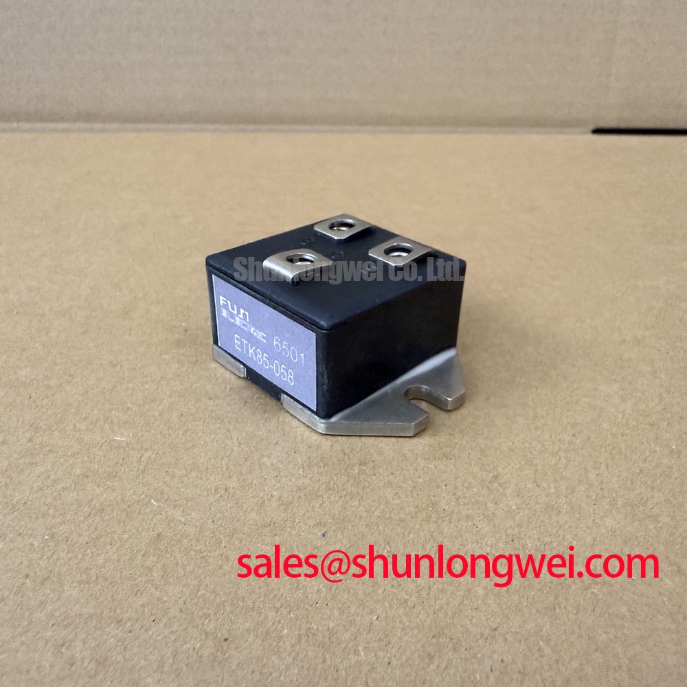
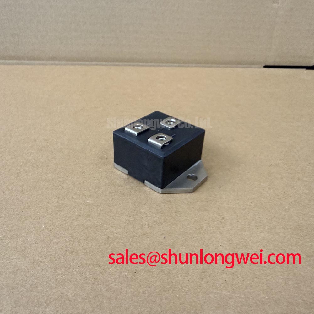
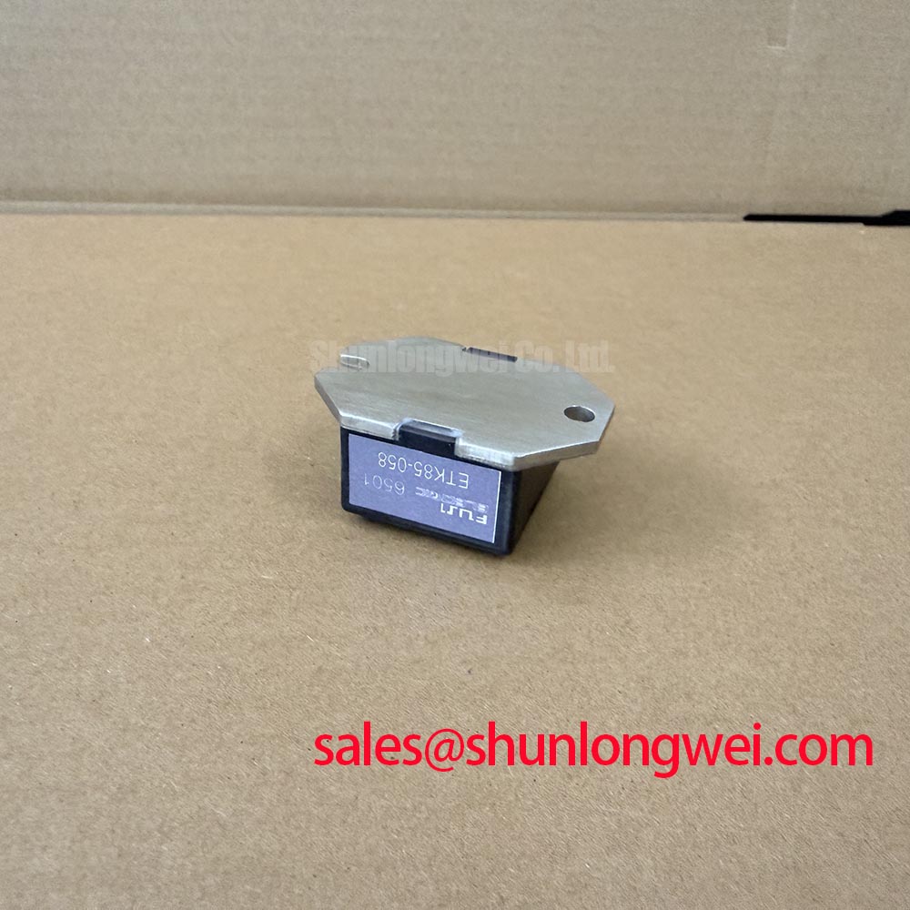
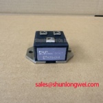
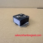
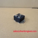
With the rectifier isolated and discharged, check the ETK85-058 terminal markings against the replacement drawing, then compare cold-state diode junction readings with a known-good reference before reconnecting the DC bus. The device is identified as a Fuji Electric ETK85-058 diode module. Verified numerical voltage and current ratings are not provided here, so confirm those limits against the manufacturer’s documentation and the original equipment requirements rather than inferring them from the model number.
For a high-current green hydrogen electrolyzer DC power rectifier, the practical evaluation begins at the terminals. Confirm polarity, busbar orientation, insulation condition, and the intended fuse coordination before applying power. A diode-test measurement is useful for detecting an open or unexpectedly conductive junction, but the reading should be interpreted as a comparison between identical test conditions, not as an unqualified acceptance threshold. Keep the module protected from electrostatic handling during incoming inspection. 💡 Bench Tip: Use an ESD-controlled workstation and record cold-state readings before mounting the module, because thermal conditions and connected snubber networks can alter the measurement.
In a six-pulse bridge, each phase group conducts in sequence, while a twelve-pulse arrangement uses phase-shifted secondary windings to distribute commutation events and reduce characteristic ripple components at the DC output. The ETK85-058 should therefore be assessed as part of the complete bridge leg, not as an isolated current rating. In a rectifier with parallel converter groups and an interphase transformer, that transformer helps the groups share current. Its winding polarity, leakage characteristics, and connection symmetry should be checked against the system schematic before replacing a module.
Terminal connections require particular attention because uneven busbar contact can create local heating and unequal current paths. Clean mating surfaces, maintain the original conductor arrangement, and use the manufacturer’s specified fastening torque for the module terminals and mounting hardware. The fuse selection should be coordinated with the module’s published surge and I²t data. Where a fuse I²t coordination table is supplied for the equipment or replacement assembly, compare the prospective fault energy with that table rather than substituting a fuse solely by continuous current.
For rectifier cabinets feeding electrolyzer stacks, designers should also inspect the laminated busbar path and commutation loop. Minimizing parasitic loop inductance is a Design Consideration for reducing turn-off overshoot during rapid current transfer; the resulting peak voltage must be verified against the actual DC-link conditions during controlled switching tests. If a fault report includes overcurrent or short-circuit alarms, the distinction between those events can be reviewed in IGBT overcurrent and short-circuit fault analysis, even though this product is a diode module.
Benchtop Waveform Tuning: Evaluating Temperature-Dependent Reverse-Recovery Stress on ETK85-058
Reverse-recovery behavior should be evaluated at the bridge operating point where diode current commutates into the next conducting path. Probe placement must capture the actual diode terminal voltage and commutation current without adding a long measurement loop. Where available, use the published reverse-recovery specification, including any stated recovery time, peak recovery current, charge, and test conditions. Do not transfer values from another Fuji Electric family or assume that a visually similar module has the same soft-recovery behavior.
Temperature changes can shift reverse-recovery charge and the associated current peak. A controlled bench comparison should therefore keep any surrounding converter gate or firing control, source impedance, bus voltage, load current, and heat-sink condition consistent while the waveform is recorded. A harder recovery profile may increase commutation stress, ringing, and radiated interference; a softer profile may alter switching loss and thermal distribution. The correct acceptance window is the one established by the module data and the equipment test plan.
Snubber placement, diode bridge symmetry, and the return path to the DC-link capacitor should be reviewed together. If the rectifier uses a front-end device family from another supplier, including components associated with Freescale Semiconductor, evaluate the combined commutation behavior rather than treating each supplier’s data sheet as a complete system model. The ETK85-058 package should be mounted against a clean, flat thermal interface, with the original electrical clearances preserved around high-voltage terminals.
Field Diagnostics & Commissioning: Power Factor Degradation and Harmonic Mitigation in Rectifier Systems Using ETK85-058
Where the equipment includes a phase-controlled converter stage, commissioning should correlate its firing-angle commands with line current, DC output, reactive demand, and harmonic content. Across a controlled firing range extending from near-zero delay toward deep retard operation, the controlled bridge transfer characteristic changes with source impedance, overlap, load state, and transformer configuration. A diode module itself has no firing-angle control. The ETK85-058 does not establish the cabinet’s power factor or harmonic compliance; those results belong to the complete converter topology and its control strategy.
For six-pulse equipment, inspect phase-current balance and line-current distortion at the intended electrolyzer load. For twelve-pulse systems, verify transformer phase displacement and, where applicable, interphase transformer sharing before attributing poor power factor to the diode assembly. An oscilloscope, power-quality analyzer, and thermal survey can be used together to identify whether commutation notches, unequal phase conduction, loose terminals, or an overloaded cooling path are contributing to the observed behavior.
High-voltage rectifier maintenance also requires deliberate separation distances at the module terminals. Preserve the original creepage and clearance arrangement, prevent conductive contamination, and route measurement leads away from switching and busbar edges. The same discipline applies to regenerative braking choppers, high-power braking resistors, bidirectional battery DC-to-DC converters, and long motor-cable installations where reflected-wave peaks may increase terminal stress. These are Design Considerations for the surrounding system, not additional factory ratings or confirmed applications for ETK85-058. For a broader service reference covering power semiconductor selection and switching reliability, consult the Power Electronics Masterclass.
For package and thermal-interface context, engineers may also consult Fuji Electric’s power semiconductor resources and the background discussion of silicon nitride ceramic substrates. These references support general assembly evaluation and should not be read as additional ETK85-058 specifications.