

Content last revised on October 17, 2026
Field Diagnostics & Commissioning: Evaluating Thermal Capacitance vs Heat Sink in FF200R12KE3G Topologies
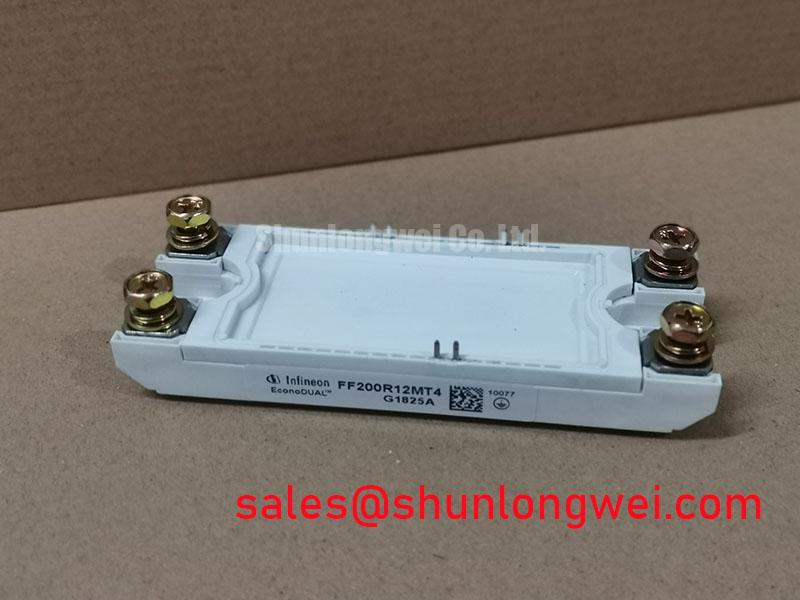
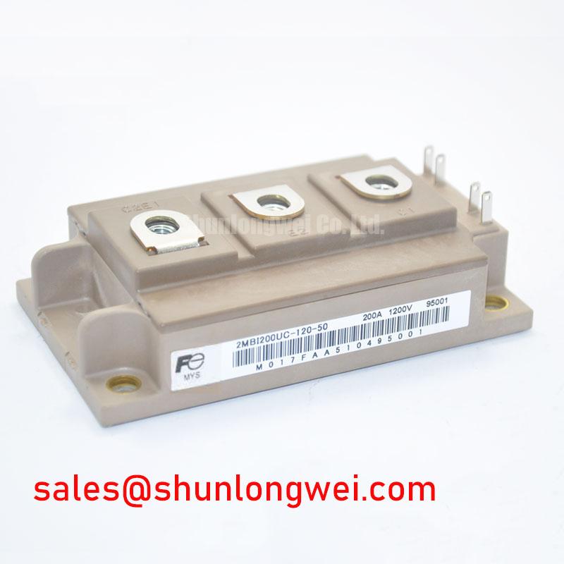
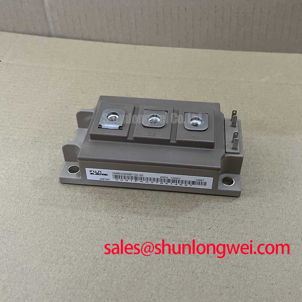
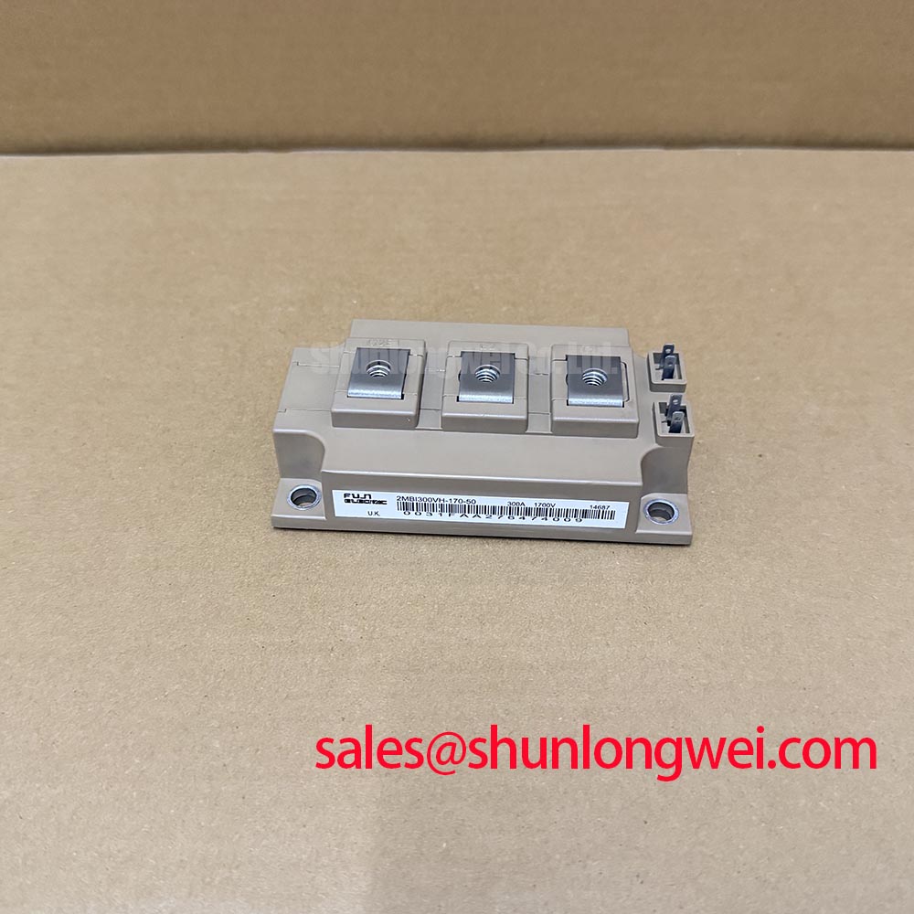
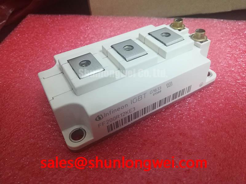
With the DC link isolated and verified discharged, compare the module identification and terminal arrangement with the equipment schematic before reconnecting the power stage. The FF200R12KE3G is an Infineon IGBT Module with a 1200 V collector-emitter voltage rating and a 200 A current rating under the specified datasheet conditions. Its package classification is Module. These ratings establish the component identity; commissioning also requires the applicable datasheet conditions, terminal drawing, and equipment protection settings.
Capture the load-pulse duration, repetition pattern, and case-temperature trend before attributing a thermal trip to inadequate heatsink capacity. As a Design Consideration, short overloads involve transient junction-to-case thermal impedance, whereas sustained operation increasingly involves the thermal interface, heatsink, and cooling airflow. A case sensor can therefore show a modest temperature change while the semiconductor junction experiences a substantially faster excursion.
For an Engineering Calculation, use the manufacturer’s transient thermal-impedance curve or a corresponding documented multi-RC model. Each thermal branch contributes a time-dependent response; applying the measured or calculated dissipation waveform to that response gives the junction-to-case temperature rise. Add the case-temperature boundary condition to estimate peak junction temperature, then compare it with the applicable datasheet limit. Repeated pulses require accounting for residual heat rather than treating every pulse as a cold start. Model coefficients and temperature limits must come from the device documentation, not a similarly rated module.
During maintenance, examine blocked cooling fins, fan performance, heatsink contact condition, and temperature-sensor attachment before changing overload settings. As a Design Consideration, a rising case temperature across otherwise comparable duty cycles warrants checking the complete cooling path; it does not isolate the module as the cause. Set inspection intervals from operating hours, contamination exposure, and recorded temperature trends rather than assigning an unsupported replacement lifetime.
Maintenance Note: Trend terminal temperature rise and check cooling airflow during scheduled maintenance before returning the assembly to its established duty cycle.
FF200R12KE3G Thermal-Electrical Optimization: Auxiliary Emitter Pinout Cold-Check Practical Tuning
Trace the gate-driver return against the terminal drawing before accepting continuity between emitter connections as proof of correct wiring. As a Design Consideration, where the documented arrangement provides an auxiliary emitter connection, the driver return should follow that designated connection rather than share the load-current return path. Cold continuity testing can establish connectivity, but cannot demonstrate low shared inductance during switching.
Keep the gate-drive loop separate from the main commutation loop and assess gate-emitter voltage at the relevant module terminals during controlled testing. Shared emitter inductance can disturb the voltage seen by the driver as load current changes. Correlate any apparent gate disturbance with collector current and switching-node activity, using probes suitable for the measurement environment; probe-loop pickup can otherwise resemble a real switching problem.
Mechanical assembly also affects the thermal boundary used in commissioning. As an Engineering Recommendation, inspect heatsink flatness and cleanliness, apply the thermal-interface material according to the approved assembly procedure, and tighten mounting fasteners progressively in the specified sequence. Neither a universal interface thickness nor a generic screw torque should replace the package-specific mounting instructions. Inspect terminal supports and busbar alignment so tightening does not impose avoidable mechanical loading on the module.
For compatibility assessment, industrial inverter welders and medium-frequency induction-heating supplies are potential evaluation contexts, subject to circuit and thermal verification. A comparison with FS200R12PE4 should examine circuit configuration, terminal mapping, mounting geometry, gate-drive requirements, and loss characteristics—not treat matching headline ratings as interchangeability. The Infineon IGBT Modules & Discretes Official Portfolio provides manufacturer context for distinguishing device families.
Transient Dynamics & Electrical Design: Driver Power Stage Start-Up Inrush Mitigation on FF200R12KE3G
Verify that the gate-driver supply, undervoltage lockout, and hardware inhibit reach their intended states before the power stage can switch. As a Design Consideration, any negative turn-off bias belongs to the validated driver design and device limits; it should not be assigned from a generic voltage range. Observe startup and shutdown transitions, including auxiliary-supply collapse, to check that the gate remains controlled throughout the sequence.
Separate DC-link charging behavior from gate-drive readiness during troubleshooting. Precharge limits capacitor charging current, while driver interlocks prevent unintended switching; neither function substitutes for the other. Minimize commutation-loop inductance through appropriate busbar geometry to reduce turn-off overshoot, then evaluate measured voltage peaks under the equipment’s operating conditions. Maintain terminal creepage and clearance according to the applicable equipment insulation design, including contamination and condensation exposure.
For resonant-load troubleshooting, Resonant Topologies in Home Appliances offers a topology comparison, not proof of this module’s application suitability. Check the actual schematic before interpreting switching waveforms. If an upstream controlled rectifier uses thyristors, its trigger-current requirements and firing-angle controls are separate from the IGBT gate driver. Diagnose charging, rectifier firing, and inverter enable as distinct functions so a startup fault is not assigned to the FF200R12KE3G without supporting measurements.