
Content last revised on September 25, 2026
Benchtop Waveform Tuning: Mitigating Stress via SCSOA Overcurrent Protection: Implementing on FSAM30SH50A
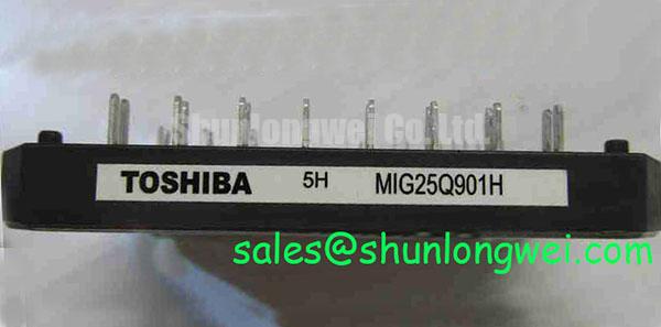
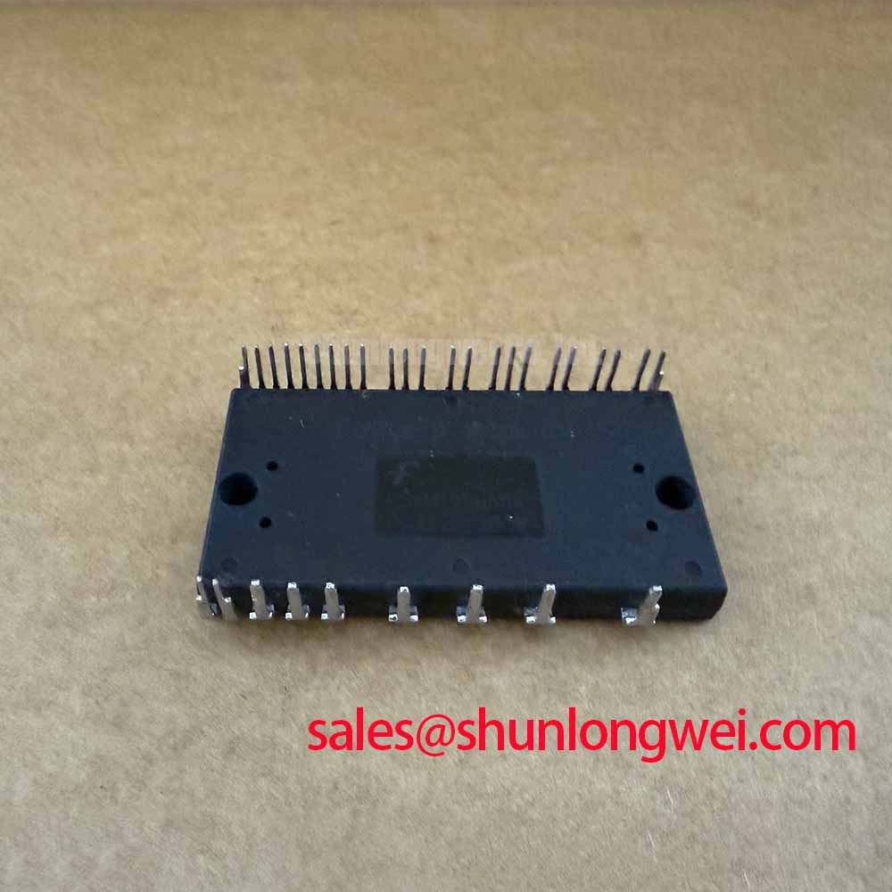
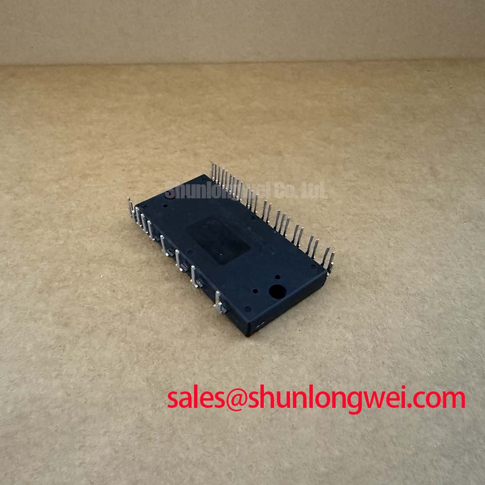
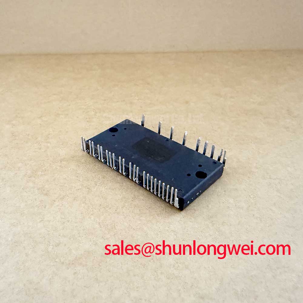
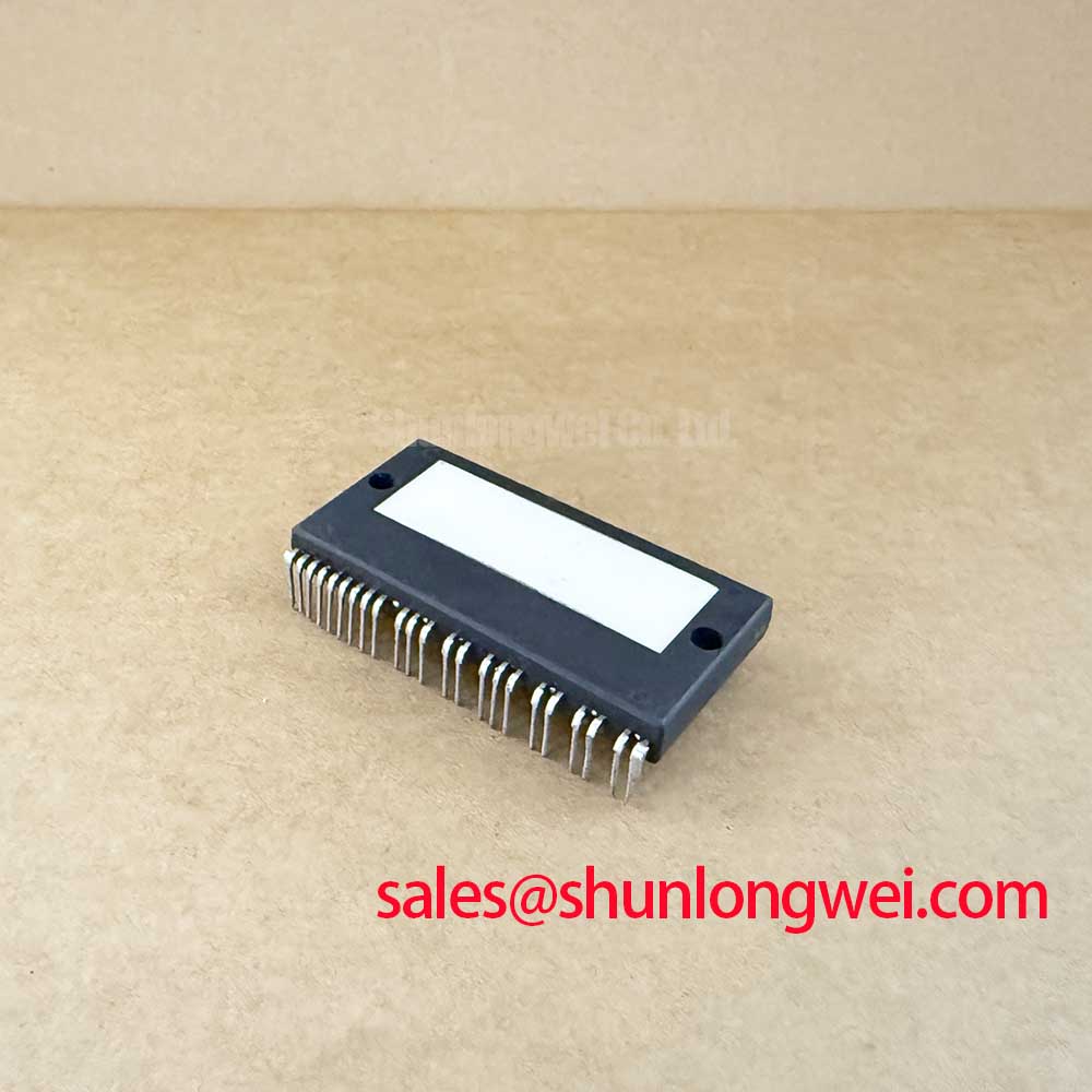
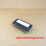
With the DC link fully discharged, begin incoming inspection by checking the module marking against the service record, then compare the power terminal paths and control connector orientation with the original inverter documentation before any energised test. The FSAM30SH50A from Fairchild Semiconductor is specified at 500V collector-emitter voltage, with 2500Vrms isolation voltage for 60Hz and 1 minute. Its control interface is specified as 3.3V and 5V logic compatible, while the documented short-circuit trip level is 0.45V to 0.55V.
| Parameter | Official Specification |
|---|---|
| Manufacturer | Fairchild Semiconductor |
| Product Model | FSAM30SH50A |
| Product Category | IGBT Module |
| Collector-Emitter Voltage | 500V |
| Isolation Voltage | 2500Vrms, 60Hz, 1 minute |
| Input Logic Compatibility | 3.3V and 5V compatible |
| Short-Circuit Trip Level | 0.45V to 0.55V |
For a repair bench, confirm that the inverter control board presents valid logic states at the FSAM30SH50A input before applying the intended DC bus voltage. The official input threshold compatibility with 3.3V and 5V logic helps define the expected controller interface, but it does not replace verification of the original gate drive timing, enable sequence, interlock logic, or fault reset behaviour. A controller that can communicate at the correct logic level can still create damaging switching conditions if its complementary command paths are not correctly sequenced.
The module documentation identifies a short-circuit trip level of 0.45V to 0.55V. This value should be treated as an official specification for the module protection reference and checked against the surrounding control circuit rather than interpreted as a complete system protection threshold. In a motor inverter, the observed response after an overcurrent event depends on the current sensing arrangement, controller firmware, wiring inductance, DC link condition, and shutdown sequence. When evaluating a board, engineers should capture the fault reference, command outputs, and DC bus waveform together so the event can be understood as one switching system.
Type I and Type II short-circuit events are often discussed as different stress conditions because one can occur during normal conduction while another may arise from a commanded or externally induced phase-leg fault. Design Consideration: the protection path should remove the switching command quickly enough to remain within the applicable short-circuit safe operating boundary, while the turn-off path should avoid an excessive inductive voltage rise. The maximum permissible protection timing and switching response must be verified from the complete inverter design documentation and measured on the actual hardware.
A two-stage turn-off strategy is frequently evaluated where the drive system initially reduces current in a controlled manner, then holds the affected switch in a defined off state. This is an Engineering Recommendation rather than an official factory setting for this model. Its purpose is to balance fault interruption against voltage overshoot across the semiconductor. Keep the high-current commutation loop compact, preserve isolation distances required by the assembled equipment, and inspect busbar joints, capacitor connections, and phase terminals for movement or heat damage that could add unwanted inductance.
💡 Bench Tip: Use ESD controls and compare cold-state diode-mode readings with a known-good inverter path before interpreting a single reading as evidence of a module fault.
For electric material handling or forklift low-voltage traction equipment, a no-run condition can originate in the control board, contactor circuit, motor harness, current sensor, or the power module. A static diode-mode check can help identify gross asymmetry among phase paths, but it cannot validate dynamic protection. If one phase looks different, isolate the motor and external cabling where practical, then compare control board signals with a known-good channel using an appropriately rated oscilloscope arrangement.
Benchtop Waveform Tuning: Mitigating Stress via Sizing Braking Resistors and Chopper Transistor on FSAM30SH50A
During traction motor deceleration, mechanical energy can return to the DC link. Whether that energy is absorbed by a braking resistor, battery path, chopper circuit, or another system-controlled route is determined by the original equipment topology. The FSAM30SH50A should therefore be evaluated within the actual inverter architecture rather than assigned a braking function solely from its voltage rating. Its official 500V collector-emitter rating provides a defined device boundary, while the permissible DC-link operating envelope remains a system-level decision supported by transient measurements.
Design Consideration: braking resistor selection must account for the energy released during deceleration, the allowed DC-bus rise, repetition pattern, enclosure heat dissipation, resistor pulse capability, and the control strategy that commands braking. The brake chopper transistor and resistor must also be assessed as a pair. A resistor with inadequate pulse handling can overheat even if the chopper switch itself appears to function, while a delayed chopper command can allow the DC link to rise before energy is redirected.
On the bench, begin by checking whether the brake command is generated by the vehicle controller or an inverter board comparator circuit. Then monitor the DC bus and braking control path during a controlled deceleration event. An unexpected bus excursion may be related to a disabled chopper, open resistor wiring, poor battery acceptance, control logic inhibition, or switching noise affecting the threshold signal. These possibilities need measurement-based separation rather than a single assumed cause.
Freewheeling diode reverse recovery can influence switching voltage shape and conducted or radiated noise. A sharply changing recovery current can interact with wiring and bus inductance, producing ringing that is visible at the power terminals. Design Consideration: snubber networks, capacitor placement, terminal geometry, and gate-drive behaviour should be assessed together when waveform ringing is present. The system engineer should validate peak-voltage margins against the DC-link voltage during switching tests, using measurement methods suitable for the equipment voltage and bandwidth.
Conformal coating and solder mask can affect contamination resistance and surface insulation performance around supporting PCB circuitry, although they do not substitute for correct power layout or terminal spacing. For reference, the role of printed circuit board solder mask and conformal coating is relevant when inspecting traction inverter control boards exposed to moisture, conductive dust, or cleaning residues. Check for cracks, residue, lifted copper, and damage around the current-sense and brake-control circuits before attributing an unstable braking waveform to the module.
Where a higher-voltage, higher-current power stage is being reviewed for a different system platform, the FZ3600R12HP4 is a separate power semiconductor reference that should be compared only against the original system electrical, thermal, mechanical, and control requirements. It is not a direct replacement determination for the FSAM30SH50A.
FSAM30SH50A Thermal-Electrical Optimization: Cosmic Ray Robustness: Voltage Derating and Practical Tuning
The 500V collector-emitter rating is an official specification, but it must not be converted into an unsupported claim about lifetime, altitude operation, terrestrial neutron robustness, or single-event burnout performance. No field failure rate, FIT figure, cosmic-ray susceptibility value, or altitude-derating figure is stated here for the FSAM30SH50A. These topics require manufacturer-supported qualification data and system-specific environmental analysis.
Design Consideration: installations at elevated locations can change cooling conditions and may alter the electrical environment that a complete traction inverter experiences. Engineers evaluating forklift or warehouse vehicle equipment should review the original equipment environmental limits, enclosure airflow, contamination conditions, DC-bus transients, and the stated ratings of all connected components. The module’s 2500Vrms isolation rating at 60Hz for 1 minute is an official dielectric test specification, not a blanket declaration of application-level insulation coordination, operating pollution degree, or safety certification.
Voltage derating is best addressed through measured operating stress rather than a universal percentage. The relevant evidence includes DC-bus value, commutation overshoot, temperature, switching frequency, motor-lead behaviour, fault response, and the condition of the DC-link capacitors. When a waveform approaches a design boundary, investigate the loop geometry and switching behaviour before changing hardware values. The final acceptable operating margin is determined by the complete system design and should be confirmed through controlled testing.
For long-term maintenance planning, avoid assigning a service life to the module from elapsed operating hours alone. Temperature cycling, loading pattern, cooling performance, vibration, contamination, and fault history can all affect an inverter assembly. A useful inspection record includes heatsink condition, interface material condition, terminal tightness, bus capacitor health, fan operation where present, and repeated waveform comparisons taken under equivalent load conditions.
Simulation can help correlate measured switching and thermal conditions with a system model, but model output is only as reliable as the parameters and boundary conditions entered. Engineers using SPICE simulation should validate the model against captured waveforms from the actual inverter rather than assuming generic device models reproduce the installed hardware. The broader methods used to review IGBT selection, switching stress, and reliability are discussed in the Power Electronics Masterclass.
For comparison during a procurement review, the FS200R06KL4 is another Infineon power semiconductor reference. Electrical rating, package interface, protection architecture, cooling method, drive compatibility, and original equipment documentation must all be reviewed before any substitution decision is made.
Assembly Integrity & Layout Architecture: Implementing Junction-to-Case Thermal Network Simulation for FSAM30SH50A
Before replacing an inverter module, inspect the heatsink mating surface, mounting plane, power terminal alignment, control connector seating, and thermal interface residue. A thermal problem can be created by warped mounting surfaces, uneven clamping, aged interface material, blocked airflow, or a loose busbar connection even when the semiconductor passes basic static checks. The FSAM30SH50A should be mounted only according to the mechanical instructions and torque requirements of the original equipment documentation, because no mounting torque or thermal resistance value is established here as an official parameter for this model.
A junction-to-case thermal network model represents heat flow through several time-dependent paths rather than a single instantaneous temperature change. Engineering Recommendation: use the manufacturer-approved thermal impedance information when available, combine it with measured case or heatsink temperature, and apply the actual load pulse profile from the equipment. This approach can help estimate whether a pulsed overload event is likely to create excessive junction stress, but it must not be presented as a measured junction temperature without validated device data and test conditions.
In practical troubleshooting, capture temperature rise alongside current, DC-bus voltage, phase-current command, and cooling-system behaviour. A rapid temperature increase may indicate excessive switching loss, abnormal conduction loss, inadequate heatsinking, poor thermal transfer, or a load condition outside the expected operating profile. Comparing equivalent phases and repeating measurements after correcting obvious mechanical issues is more reliable than drawing a conclusion from one thermal image or one current trace.
The 2500Vrms isolation specification should be respected during system inspection. Do not apply improvised insulation tests through connected low-voltage control electronics, current sensors, communications circuits, or capacitors without following the original equipment test procedure. Review cable routing and connector strain relief so vibration or service movement does not transfer force into the module terminals or control interface.
For forklift traction inverter repair evaluation, verify that the replacement part number, voltage class, connector arrangement, cooling interface, and controller logic requirements match the original assembly. The official 3.3V and 5V compatible input logic specification and 0.45V to 0.55V short-circuit trip level are important reference points, but a safe return to service also requires validation of the complete inverter, motor circuit, braking path, and protective control response.