

Content last revised on November 10, 2026
Preventing Spurious Faults: Turn-On Current Rise Limiting Guidelines for HD4890
Isolate the power stage, discharge stored energy, and disconnect parallel circuit paths before comparing the cold-state terminal measurements of an HD4890 with the equipment schematic. Record measurement polarity and instrument mode rather than treating a single resistance reading as a pass or fail result. Semiconductor paths, suppression components, and connected control circuitry can influence the reading.
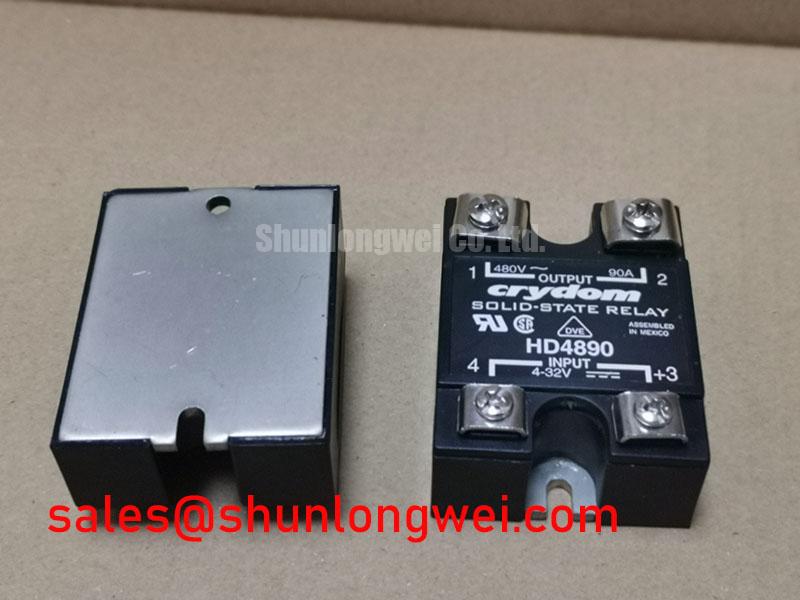
The product identification and selection baseline is: Manufacturer: Crydom; Part Number: HD4890; Rated AC Load Current: 90 A, subject to the manufacturer's thermal and mounting conditions; Device Type: AC-output solid-state relay. The HD4890 should not be identified as a bare thyristor/diode module, and its AC load-current rating is not an average on-state current, IT(AV), rating. Specification checkpoint: load-voltage range, blocking voltage, current-rating conditions, terminal assignments, control-interface characteristics, surge ratings, and mounting torque—consult the datasheet. “Standard Industrial Rating” is not a numerical reverse-voltage limit and should not be entered as one in a purchasing specification.
Trace the actual control terminals before connecting test equipment or changing suppression components. Design Consideration: a solid-state relay control input must not be treated as an exposed thyristor gate. Do not assume that the HD4890 provides access to internal triggering circuitry.
Where the circuit exposes thyristor triggering, examine the relationship between the trigger command, device voltage, and load-current rise. Excessive off-state voltage slew can promote unintended conduction, while excessive current rise immediately after triggering can concentrate dissipation before conduction spreads. These are different stresses: an RC snubber intended to control voltage slew does not automatically provide adequate current-rise limitation.
As a Design Consideration, evaluate snubber resistance and capacitance against measured ringing, repetitive dissipation, and discharge current at turn-on. A series saturable reactor requires separate assessment of saturation behavior, reset conditions, and interaction with the load. Component values should follow the equipment waveform and applicable device limits, not the current rating alone.
For an accessible gate circuit elsewhere in the equipment, compare trigger-current and trigger-voltage requirements with the driver waveform under operating conditions. Pulse-train triggering is a system option only where the device interface supports it; stronger triggering must remain within gate limits. Minimize shared power and control return paths to reduce interference during commutation.
Practical reminder: Keep suppression connections close to their intended terminals, and verify their effect with safely acquired switching waveforms before returning the equipment to service.
HD4890 Circuit Protection & Reliability: Assessing Use in AC-to-DC Systems
Identify the complete bridge arrangement and control method before interpreting the relationship between AC input and DC output. The HD4890 is an AC-output switching relay, not a complete rectifier or an exposed-gate phase-control module. Design Consideration: firing-angle analysis applies to a phase-controlled converter, not automatically to every module containing thyristors. A zero-crossing switching interface, for example, cannot be assumed to provide continuously adjustable firing-angle control.
Where the equipment genuinely provides phase control, compare commanded firing angle with measured conduction onset, average DC output, ripple, and line current. Delayed conduction changes the current waveform; the resulting power factor includes distortion as well as displacement effects. Reactive-power demand therefore needs assessment at the converter input rather than inference from average output voltage alone. Discontinuous load current and commutation overlap can also change the transfer characteristic.
A high-current green hydrogen electrolyzer DC power rectifier is one possible system-level compatibility assessment for AC-side switching, subject to the converter architecture, control interface, cooling arrangement, and operating envelope. The relay’s stated AC current rating does not establish the complete rectifier output capability or suitability for switching DC.
For replacement assessment, compare terminal functions, circuit configuration, blocking capability, control behavior, thermal interfaces, and mounting dimensions. The SKKT 20/14E is a different device type and must not be treated as a direct replacement for the HD4890 solid-state relay; any use would require a separate circuit-level engineering assessment. Similarly, the B612F-2T can be assessed separately where the equipment schematic calls for a complementary power-stage component; the link does not establish compatibility.
Fuse coordination requires matching the manufacturer’s semiconductor withstand conditions against fuse clearing characteristics at the prospective fault current. Compare surge-current duration, initial junction temperature, and permitted I²t conditions together. A nonrepetitive surge rating does not authorize repeated overloads, and the allowable recovery interval depends on the actual thermal history.
Benchtop Waveform Tuning: Mitigating AC Line Surge and Lightning-Transient Stress on HD4890
Coordinate upstream surge protection with the voltage actually reaching the module terminals. Design Consideration: MOV selection involves continuous operating voltage, clamping behavior, pulse-energy duty, protective-device coordination, and end-of-life behavior. An RC network addresses a different part of the transient response and should not be treated as a substitute for appropriately coordinated surge protection.
IEC 61000-4-5 describes equipment surge-immunity testing; it does not establish an HD4890 immunity rating. Applicable test levels, coupling arrangements, and acceptance criteria belong to the equipment specification. Laboratory evaluation should capture residual terminal voltage and the control response without exceeding the module’s documented limits.
Inspect terminal spacing, contamination, damaged barriers, and cable positioning against the equipment insulation design. Creepage and clearance depend on the applicable voltage and environmental classification; package appearance alone cannot establish compliance. Apply the specified fastening procedure separately to power terminals and mounting hardware rather than assuming interchangeable torque requirements.
For recurring thermal trips, inspect heatsink contact, interface condition, airflow, and connection heating before attributing the fault to semiconductor degradation. The Thermal resistance Application Guide offers general thermal-path background, not HD4890-specific limits. Repeat controlled operating measurements after correcting assembly defects, recording case temperature, load conditions, and protection behavior against the equipment’s acceptance criteria.