Shunlongwei Co. ltd.
IGBT Module / LCD Display Distributor
Customer Service
+86-755-8273 2562
IGBT Module / LCD Display Distributor
“Wearable devices are rapidly emerging as an important market area for Electronic components. A key requirement of this type of equipment is convenience, not only in terms of being able to access data on moving objects, but also ensuring that the battery has enough battery life for a full day every day.
“
Wearable devices are rapidly emerging as an important market area for Electronic components. A key requirement of this type of equipment is convenience, not only in terms of being able to access data on moving objects, but also ensuring that the battery has enough battery life for a full day every day.
If the user has to plug in the device to charge it overnight, sometimes it is very likely that he forgets to charge and only wakes up to find that the device will be unusable for the next day. The wireless charging function brings a more convenient way of charging electronic devices. When performing wireless charging, only the electronic device needs to be placed on the charging pad, and there is no need to insert a micro USB or similar cable into the device to be charged, and the user can put the charging pad in a place that is easy to reach. If the wireless charging system is properly designed, one charging pad can charge multiple devices at the same time, without charging one by one, and it is more convenient for users to go out and carry the charging pad and devices.
Now, it is not just wearable devices that enjoy the convenience of wireless charging. This technology has already been widely used in electronic toothbrushes, and is even being scaled up to charge electric car batteries.
The basic working principle of inductive charging is the same as that of a power transformer. The induction coil in the charging pad generates an alternating electromagnetic field, and then the coil of the device to be charged receives the electromagnetic field and converts it into a useful current again. Similar to traditional transformers, basic inductive charging also requires two coils to be in close proximity to obtain high efficiency. Otherwise, the resistance in the primary coil will generate considerable accumulated losses.
Using two coils to generate resonant inductive coupling can improve the efficiency of long-distance energy transmission. The specific method is to tune the two coils by combining inductive and capacitive loads to make them resonate at the same frequency. Under such resonance conditions, a large amount of electrical energy can be transferred from one coil to another coil located at several times its diameter.
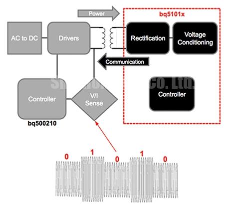
Figure 1: Load modulation is used to encode data during transformer coupling.
The Q value of the coil Circuit can be adjusted higher to establish a relatively strong magnetic field after multiple cycles. The electric energy carried in this oscillating signal is higher than the electric energy fed into the coil at any one time. Since the secondary coil can receive a part of this oscillating magnetic field and convert it, the output power is higher than that of a traditional transformer. The use of tuned capacitors to achieve resonance can eliminate the stray and magnetizing inductance in the transmitter, thereby fundamentally reducing the resistance loss of the coil winding, which is usually 10 to 100 times the inductive loss.
In order to make the Q value higher than the traditional transformer, the coil is usually designed with a solenoid, which also helps to minimize the skin effect. Generally, using small dielectric constant inductors or relying on air alone can minimize dielectric loss.
In practice, the coil is not always tuned to a precise resonance frequency. As long as the secondary coil intercepts a certain amount of magnetic field lines, the loosely coupled system can transmit electrical energy. Tighter coupling through more precise coil matching can provide higher power, but for coils designed to work at the same time under resonant conditions, it is impossible to maintain strict coupling between them. These Circuits can be designed to work only under detuned conditions, where the resonant frequencies of the receiver and transmitter are slightly different.
Unfortunately, tightly coupled coils are also susceptible to the degree of alignment, and for consumer applications where users only want to put the device on the charging pad at will to successfully charge, without having to consider the best placement direction and location, this is a problem. Therefore, the transmitter used for charging can use multiple coils. This will increase the design complexity, but the choice of location is more free. The coils do not need to be overlapped, which can simplify assembly in production, although overlapping coils can increase the density and the freedom of receiver placement.
To successfully charge different devices with a single transmitter, some standards must be adopted. There are two main standards currently in use. The Powermat system is a standard advocated by the Alliance for Wireless Power, which is designed around a loosely coupled system based on a single transmitter coil. The Qi system of the Wireless Power Consortium allows a variety of different configurations, including simultaneous loose and tightly coupled operation. Most current transmitters use a multi-coil tightly coupled configuration.
These two standards also consider energy management to ensure that the charging pad only works when the device is charging. For example, the Qi system uses a communication protocol to relay the signal on the coil to check whether there is a device and whether the device supports the Qi system. According to this standard, the transmitter can change the switching frequency on the coil from 110 kHz to 205 kHz as the main control mechanism for power delivery.
Under the Qi standard, the load is simply modulated by the coil voltage to send data to the device on the other side of the air gap. The communication from the secondary coil uses different two-phase, bit-encoding schemes, the operating frequency is constant at 2 kHz, and a start bit is added before each 8-bit transmission data. After the data is transmitted, it is the parity check and the stop bit.
Figure 2: Bi-phase encoding can achieve the ability to send binary data.
A large amount of control data can be sent. The most commonly used control data packet types include: signal strength, control error, terminal power requirements, and rectified power level. The signal strength helps to adjust the position of the device on the charging pad. When used with visible or audible signals, it can guide the user to move the device along the charging pad until the signal strength is large enough to indicate that the current power transmission is good.
The control error data packet can indicate the degree of error between the input voltage observed from the receiving coil and the required input voltage. The transmitter usually uses a control loop to adjust the voltage applied to its coil. If there are large errors, the frequency of these error packets is set to a larger value. A data packet will be sent every 32 ms until the error falls below the threshold. From this point of view, these packets are sent every 250 ms. Control error packets are very helpful in regulating power delivery. Under light load conditions, the receiver may require a higher voltage in order to overcome current transients-for example, to wake up a wearable device from sleep. When the load current is large, the portable device may require a lower voltage to avoid power loss on the LDO regulator.
When the device is fully charged or an internal fault that may damage the battery is detected, the device sends a request to stop power transmission. Power delivery is also controlled by rectified power information. This will relay the part of the power that the wearable device receives at the output of its rectifier circuit. The transmitter uses this information to determine the coupling frequency and to determine whether the receiver has reached its maximum power limit. Sending every 350 ms to 1800 ms, the transmitter will use the gap without data packets to determine whether the device on the charging pad has been removed. Rectified power information also helps to detect foreign objects.
A chipset supporting the Qi protocol and controlling power delivery has been launched. For example, Toshiba introduced the TB6865AFG device for transmitters. This highly integrated part includes an ARM Cortex-M3 processor running customer code, and a PWM controller (for power delivery) that supports an external H-bridge circuit. According to the Qi standard, the controller can control power for up to two devices and support foreign object detection.
The bq51013 device is a Texas Instruments product, designed for use on the secondary side, capable of AC/DC power conversion, rectification, and digital control functions required to send commands to the transmitter. All devices in the bq5101x series use a low-resistance synchronous rectifier, LDO, and voltage and current loop controllers.
In addition to the controller, the manufacturer also provides off-the-shelf coils that support the Qi protocol standard. These coils are designed to be used as transmitters, receivers, or both. For example, Abracon’s AWCCA-50N50 series supports both transmitter and receiver applications. The diameter of the coil is slightly less than 50 mm and the anti-magnetic performance is strong, which can protect the electronic devices inside the equipment. These designs provide a Q factor that can be selected in the range of 70 or 160, and the DC resistance in these two cases is around 20 mΩ or 70 mΩ, respectively.
For smaller wearable devices, TDK introduced the WR303050 coil and reduced its package size to 30 x 30 mm and a thickness of only 1 mm. The DC resistance at room temperature is 0.41 Ω.
To increase flexibility, Vishay Dale’s IWAS-3827 offers a choice of rectangular rather than square base surfaces, with lengths and widths of 38 mm and 27 mm, respectively. The coil has a thickness of 1 mm, a DC resistance of 0.18 Ω, and a typical Q value of 30.
How to design solutions for wireless charging of wearable devices
Figure 3: AVishay Dale coil for wireless power supply.
To provide a more integrated solution, TDK’s TMx-66-2M7 and TMx-58-2M7 can be packaged with a TI receiver chip to achieve a packaged device with a total length of 66 mm and a thickness of only 1 mm.
Other optional wireless charging devices include various WPCC and WE-WPCC series wireless charging coils provided by Würth Electronics. These coils include transmitter and receiver configurations, with a rated current of 0.8 to 13 A and a variety of sizes to meet various application requirements. We can use the Würth/TI Wireless Power Demonstration Kit (760308) to demonstrate the concept and benefits of wireless charging, which uses Würth transmitter and receiver coils.
With the expansion of the ecosystem surrounding protocols such as Qi, we can look forward to simplifying design work with more integrated solutions and designing simpler charging methods for wearable devices.
The Links: 6RI50E-080 BSM15GD120DN2