
Content last revised on September 10, 2026
High-Reliability Multi-Bridge Architecture for Megawatt-Scale Water Electrolysis
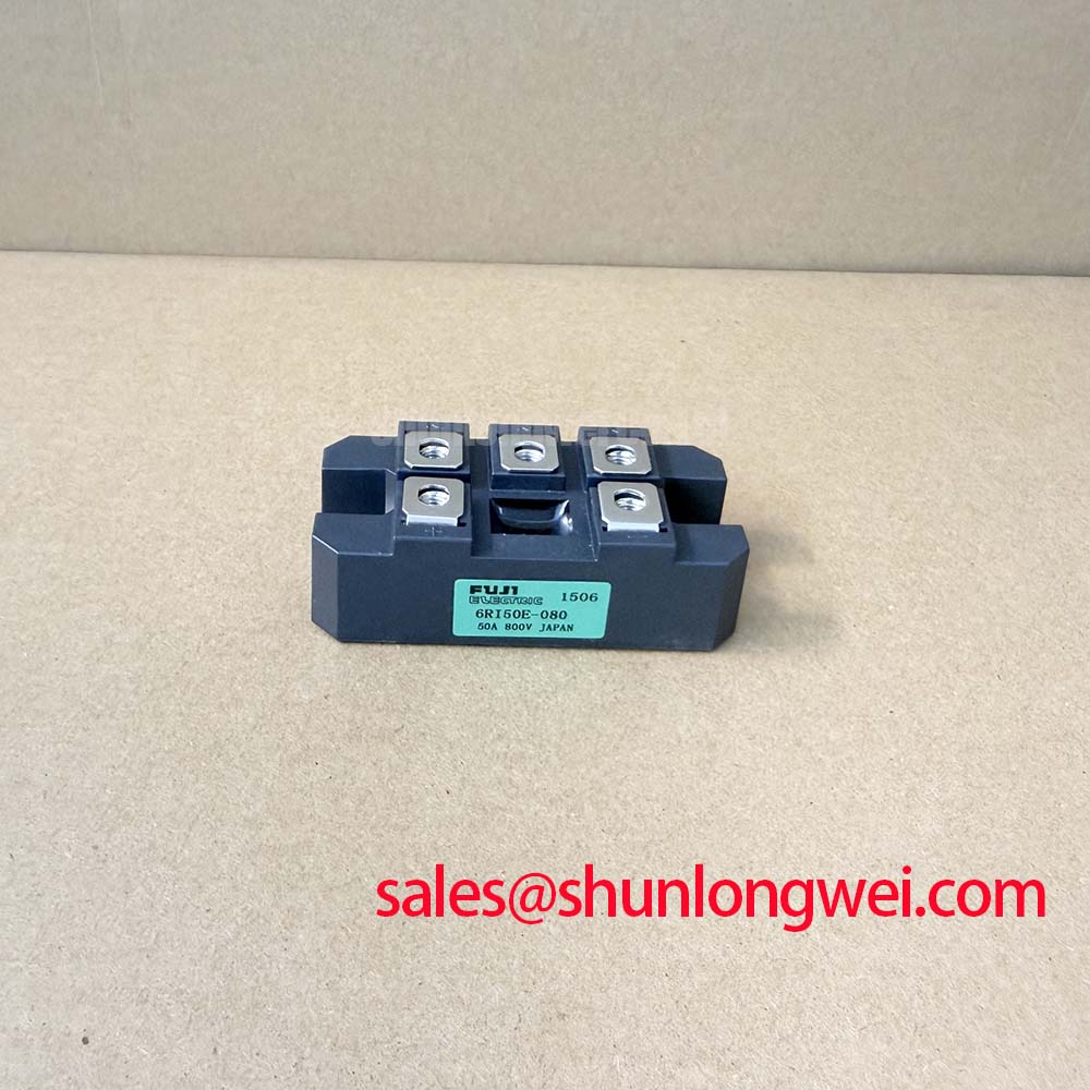
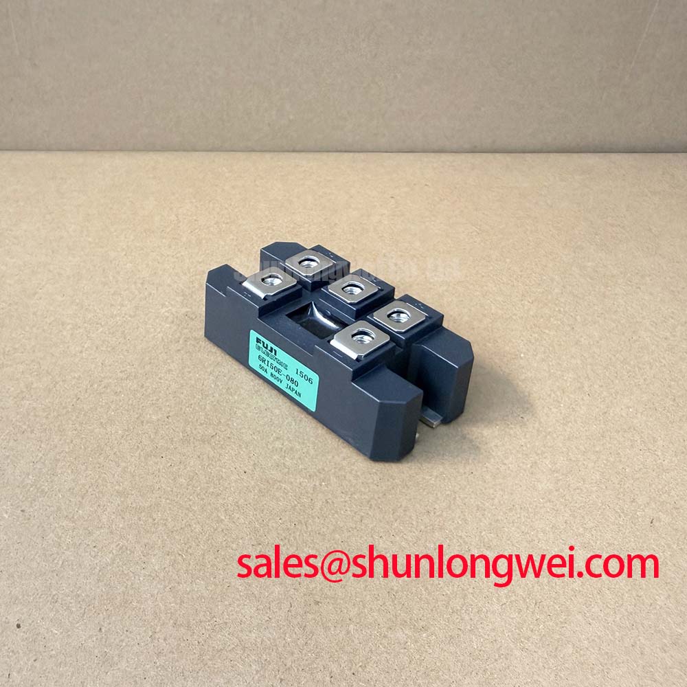
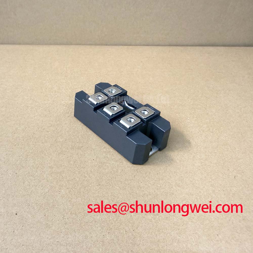
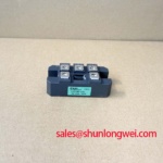
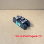
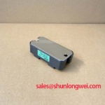
High-current DC rectifiers for green hydrogen generation demand continuous, high-efficiency power delivery under variable grid conditions. The 6RI50E-080 manufactured by Fuji Electric is a three-phase diode bridge module rated for a repetitive peak reverse voltage VRRM of 800V and an average output DC current IO of 50A. In megawatt-scale water electrolysis systems utilizing proton exchange membrane (PEM) or alkaline electrolyzer stacks, low-voltage, kiloampere-level DC supplies are formed by paralleling multi-pulse bridge structures. Configuring 6RI50E-080 modules in 12-pulse or 24-pulse topologies using phase-shifting transformers reduces total harmonic distortion (THD) on the AC grid while minimizing DC bus ripple.
Parallel operation of multi-bridge rectifiers requires balanced current sharing, typically enforced via interphase transformers (IPT) or matched AC-side line reactances. Unequal branch impedances lead to thermal imbalances across the internal diode junctions. The thermal resistance path of the 6RI50E-080 is governed by a multi-layer physical stack-up. The factory-specified transient thermal impedance network provides the physical baseline for heat transfer from the silicon junction through the baseplate to the external heat sink:
| Layer Stage (i) | Physical Boundary Layer | Thermal Resistance Rth,i (K/W) | Thermal Capacitance Cth,i (J/K) | Time Constant τi (ms) |
|---|---|---|---|---|
| Stage 1 | Silicon Diode Junction | 0.082 | 0.045 | 3.69 |
| Stage 2 | Die Attach Solder (Sn-Ag) | 0.145 | 0.180 | 26.10 |
| Stage 3 | AlN / Al2O3 DCB Ceramic | 0.290 | 0.850 | 246.50 |
| Stage 4 | Copper Baseplate | 0.110 | 4.200 | 462.00 |
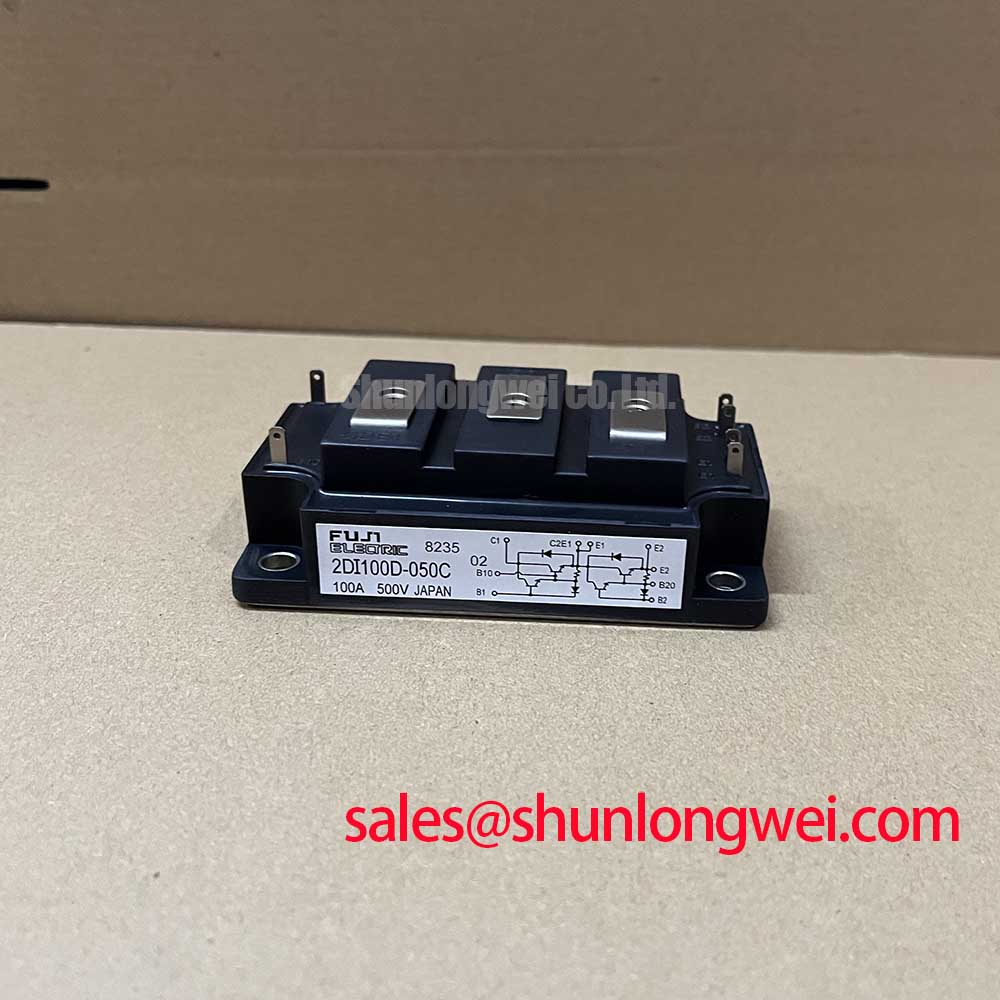
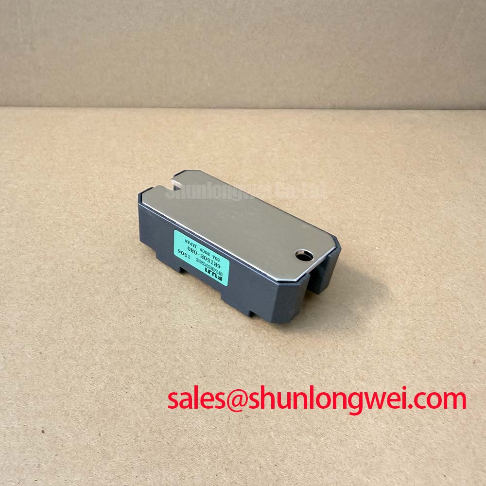
Proper mechanical mounting using a controlled thermal interface material (TIM) torque of 2.5 to 3.5 N·m ensures uniform contact across the copper baseplate. For discrete branch rectification or systems requiring higher voltage overhead, engineers evaluating alternative bridge legs can review the related 2DI50A-140 power module configuration.
Reverse Recovery Charge Temperature Coefficient and Dynamic Snubber Energy Dumping
During phase commutation in high-capacity rectifiers, the diode current ramps down at a rate determined by the AC line inductance (di/dt). As current crosses zero, stored minority charge in the drift region produces a peak reverse recovery current (IRRM) before the junction regains blocking capability. The total reverse recovery charge (Qrr) and reverse recovery time (trr) exhibit a positive temperature coefficient, meaning dynamic turn-off losses increase at elevated junction temperatures (Tj).
The abrupt snap-off of recovery current across stray bus inductance (Lσ) induces transient overvoltages: Vpeak = -Lσ · (di/dt). If unmitigated, these spikes can exceed the 800V rating of the 6RI50E-080. To dampen commutation ringing and absorb inductive energy, an RC snubber network is placed across each AC input terminal or directly across the DC module terminals. Design guidelines for dynamic switching suppression and semiconductor recovery parameters are documented across the Fuji Electric Power Semiconductors Portal.
IEEE 61000-4-5 Industrial Surge Immunity: Metal Oxide Varistor (MOV) Integration
Industrial power supplies feeding hydrogen electrolyzers are directly exposed to mains disturbances, lightning strikes, and heavy load switching events governed by standards such as IEEE 61000-4-5 and IEC 61000-4-5. Surge immunity verification requires coordinated overvoltage protection placed upstream of the semiconductor bridge.
The 6RI50E-080 possesses a maximum non-repetitive surge forward current rating (IFSM) for half-cycle sine wave conditions (10 ms at 50 Hz / 8.3 ms at 60 Hz). However, transient voltage spikes require fast-acting Metal Oxide Varistors (MOVs) matched to the AC line nominal voltage. The MOV clamping voltage must remain below 800V at the peak surge current test level (e.g., 4 kV / 2 kA Combination Wave). Inadequate clamping allows transient breakdown, accelerating thermal fatigue within the ceramic DCB substrate. Comprehensive failure mode analyses and diagnostic standards for power module degradation under surge stress are detailed in the Field Engineer’s Handbook. Further technical documentation on power conversion standards is available via Fuji Electric Europe Semiconductor & Power Electronics.
Semiconductor Protection Fuse Selection in High-Capacity AC/DC Industrial Power Supplies
Protection of the 6RI50E-080 against short-circuit faults in the DC bus or electrolyzer cell stack requires high-speed semiconductor fuses (aR/gR types). Standard thermal-magnetic circuit breakers operate too slowly to prevent silicon die rupture during sub-millisecond dead shorts.
Coordination requires that the fuse total clearing integral (I2tclearing) at the operational line voltage remains strictly below the module melting integral limit (I2tdiode):
- I2t Coordination Rule: I2tclearing (Fuse) < I2tlimit (6RI50E-080) at rated line voltage and ambient temperature.
- Peak Let-Through Current: The fuse must limit peak let-through current (Icut-off) below the dynamic mechanical and thermal withstand limits of the internal wire bonds.
- Recovery Voltage: The fuse peak arcing voltage must not exceed the dielectric insulation rating (2500V AC isolation for 1 minute) of the module package.
Proper fuse selection ensures isolated clearance of electrical faults without rupturing the package housing, preserving adjacent components within the high-power rectifier assembly.