

Content last revised on September 23, 2026
PD10M440H Operational Boundaries: Post-Surge Reverse-Voltage Blocking Limits
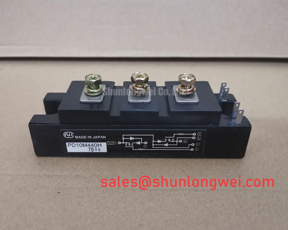
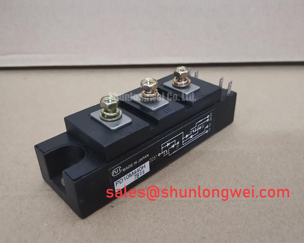
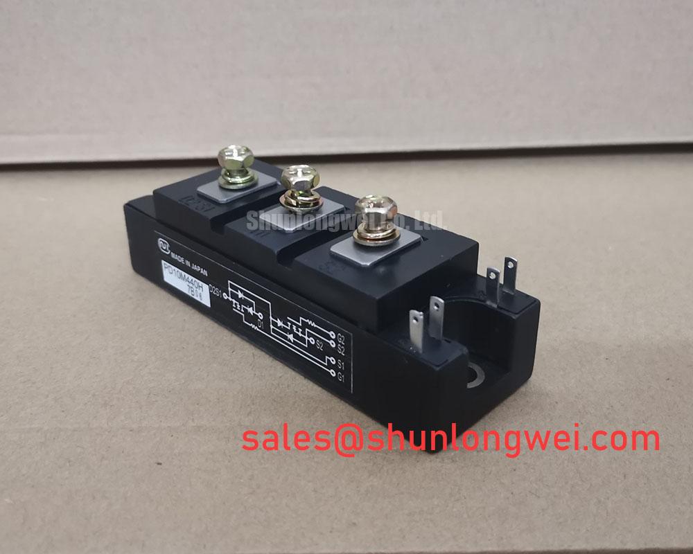
Before installation, verify the nameplate against the repair record and confirm that the replacement position requires a 4400 V, 10 A SanRex PD10M440H isolated power module. The published factory identification establishes this unit as a Thyristor / Diode Module in an isolated power module package. Terminal markings, connection orientation, and the original equipment schematic must be checked before reconnecting the main circuit, since the stated voltage and current ratings do not by themselves define the complete circuit arrangement.
| Parameter | Value | Status |
|---|---|---|
| Part number | PD10M440H | Official product identification |
| Manufacturer | SanRex, Sansha Electric | Official manufacturer identification |
| Rated voltage | 4400 V | Official Specification |
| Rated current | 10 A | Official Specification |
| Package | Isolated Power Module | Official Specification |
| Device category | Thyristor / Diode Module | Product classification |
When servicing a power cabinet after a line disturbance or fuse operation, isolate the supply, discharge the stored energy according to the machine procedure, and inspect the module terminals, housing, busbar contact faces, and adjacent protection parts before applying a reverse voltage test. The 4400 V rating is an Official Specification for the PD10M440H, but the equipment technician should not treat it as permission to apply an arbitrary test voltage or surge condition. Test limits, polarity, sequence, and instrument settings must come from the original SanRex documentation and the equipment manufacturer service procedure.
A sinusoidal surge current event and subsequent reverse blocking condition should be assessed as one system event. The available factory data supplied for this page does not establish a specific surge current rating, half cycle duration, fuse clearing value, or allowable junction temperature. Therefore, these values must be verified from the applicable manufacturer datasheet before a fuse coordination decision is made. A fuse I²t value cannot be selected from the module continuous current rating alone, because the upstream source impedance, conductor arrangement, fault path, and intended protection coordination all affect the result.
For a medium frequency induction melting or hardening furnace power supply, engineers commonly assess the AC input path, rectification section, reactor, capacitor bank, and semiconductor assembly together. This is a Design Consideration, not a statement that the PD10M440H is assigned to every such topology. Confirm whether the installed position uses the module in a line rectifier, controlled bridge, protection branch, or another circuit function before comparing parts. Where a documented repair design identifies it as a compatible direct replacement, PD104VT2T1 can be reviewed against the original schematic, terminal layout, ratings, and mounting arrangement.
PD10M440H Baseplate Thermal Resistance Guidelines
Remove loose dust from the heatsink fins and cooling path before interpreting an overtemperature alarm as a semiconductor fault. The PD10M440H is supplied in an isolated power module package, while a numerical junction to case thermal resistance is not included in the verified factory parameters provided here. It should therefore not be inferred or substituted from another SanRex module. The system integrator should obtain the applicable thermal data from original documentation and evaluate it against the actual cooling assembly.
Uniform contact between the module base and heatsink is a Design Consideration that affects heat transfer and mechanical stress. Inspect the contact plane for burrs, residue, corrosion, and uneven old thermal compound. Apply the thermal interface material in the manner specified by the equipment or material supplier, then tighten mounting hardware in a balanced sequence using the documented fastener torque. Do not impose a generic mounting torque as an Official Specification for this module when its mounting hardware and factory instruction have not been confirmed.
Maintenance Note: Monitor contact temperature rise during normal duty and verify that cooling airflow remains clear whenever thermal material or cabinet filters are serviced.
Condensation, contaminated airflow, and terminal loosening can produce intermittent behavior that resembles a thermal semiconductor problem. These conditions should be inspected separately. A measured temperature difference may indicate an interface issue, restricted airflow, changing load duty, or measurement placement error, so it should be compared with a known operating condition and the machine record rather than assigned to one cause. The product and support context available from SanRex Sansha Electric power semiconductor modules can help identify the appropriate manufacturer documentation path.
PD10M440H Transient Dynamics and Electrical Design: Gate Trigger Requirements
Check the original circuit diagram before connecting a firing source to any control terminal. Although the PD10M440H is classified as a Thyristor / Diode Module, the verified factory parameters supplied for this product do not state gate trigger current, gate pulse rise time, holding current, latching current, or a multipulse firing requirement. Those values must be taken from the correct official datasheet for this exact part and from the equipment control design. They must not be estimated from the 10 A current rating.
As a Design Consideration, the firing circuit return path should be routed and inspected as a controlled circuit path, with attention to terminal condition, connector retention, driver supply stability, and coupling from high current conductors. Parasitic inductance and poor return routing can alter the pulse observed at the device terminals, especially where a high energy power circuit shares physical space with low energy control wiring. Engineers should verify pulse form, timing, and polarity with appropriate isolated measurement equipment against the known good signal path while observing the equipment safety procedure.
Where the machine topology also contains a related input stage, PD104SL7 may be reviewed as a related system component. This link is not a substitution instruction. Its electrical function, terminal assignment, control requirements, and protection network require separate verification against the original design.
PD10M440H Circuit Protection and Reliability: AC-Line Surge Immunity and Lightning Transients
Inspect surge protective devices, snubber capacitors, resistors, wiring insulation, and grounding connections after a suspected line transient before returning the PD10M440H assembly to service. The 4400 V Official Specification describes the module rated voltage, but it does not establish system-level lightning immunity, MOV selection, RC snubber values, EMC compliance, insulation coordination, or equipment certification. Those outcomes are determined by the complete installation and require validation under the relevant system requirements.
For AC input protection, a Design Consideration is to coordinate surge limiting parts with the actual supply configuration, prospective fault behavior, fuse arrangement, and measured switching transients. MOV and RC network characteristics should be selected by the system engineer after verification of the peak conditions at the module terminals. IEC 61000-4-5 is commonly considered when defining equipment surge test requirements, but compliance cannot be claimed for an individual module without system-level evidence.
When repeated protection events occur, investigate source quality, cabinet grounding, connection tightness, cooling condition, and the recorded switching waveform. A failed or stressed accessory can coexist with a semiconductor issue, and a single visual observation cannot establish the failure mechanism. For a broader discussion of power conversion device considerations, consult The 1200 V CoolSiC™ MOSFET Advantage in Three. For comparison of industry product families and documentation routes, see Shindengen power semiconductor modules and diodes.