There’s nothing more frustrating than a shower that cycles between a powerful jet and a weak drizzle, or an industrial process compromised by inconsistent water delivery. This common problem—fluctuating water pressure—stems from the crude “all-or-nothing” operation of traditional fixed-speed pumps. They run at full power until a pressure tank is filled, then shut off completely, creating an annoying and inefficient pressure wave. Fortunately, modern power electronics have delivered a definitive solution: the variable frequency drive (VFD) controlled pump, which provides a steady, unwavering water pressure on demand. At the heart of this technological leap lies the Insulated Gate Bipolar Transistor, or IGBT.
For engineers and system designers, understanding the role of the IGBT is not just an academic exercise. It’s the key to designing, specifying, and maintaining highly efficient, reliable, and user-friendly constant pressure water systems for residential, commercial, and industrial applications. This article will deconstruct how IGBTs empower VFDs to eliminate pressure fluctuations, save significant energy, and prolong the life of the entire water system.
The Inefficiency of Traditional Fixed-Speed Pumps
To appreciate the VFD solution, we must first understand the limitations of the old method. A conventional water pump system operates on a simple principle:
- The pump motor is connected directly to the AC line, meaning it can only run at one speed (full speed) or be completely off.
- When a tap is opened, water is drawn from a pre-pressurized bladder tank.
- As the tank’s pressure drops to a pre-set low point (the “cut-in” pressure), a pressure switch slams the pump motor into action at 100% power.
- The pump refills the tank until it reaches the high-pressure setpoint (the “cut-out” pressure), at which point it abruptly shuts down.
This cycle results in a pressure that constantly fluctuates between the cut-in and cut-out points. Beyond user inconvenience, this method is plagued by two major engineering drawbacks:
- Energy Waste: The motor always runs at full speed, consuming maximum power, regardless of whether the demand is for a single dripping faucet or multiple open hoses. It’s the equivalent of flooring the gas pedal in a car just to move a few feet.
- Mechanical Stress: The violent “on-off” cycles and the resulting abrupt pressure changes cause a phenomenon known as water hammer. This hydraulic shock sends damaging jolts through pipes, fittings, and the pump itself, leading to premature wear and failure.
The VFD Solution: Introducing Dynamic Motor Control
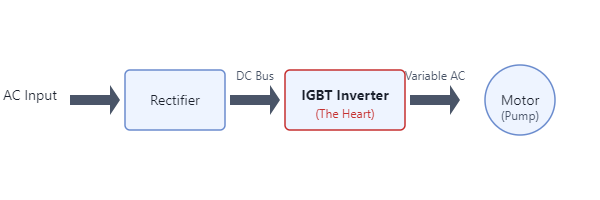
A Variable Frequency Drive (VFD), also known as an inverter, is a sophisticated power converter that sits between the power source and the pump motor. Its job is to transform the fixed-frequency AC power from the grid into a variable-frequency, variable-voltage output, thereby giving it precise control over the motor’s speed. A VFD fundamentally consists of three stages:
- The Rectifier: Converts the incoming AC power into DC power.
- The DC Bus: Smooths and stores the DC power using large capacitors.
- The Inverter: This is where the magic happens. A set of high-power IGBT modules takes the DC power and, through high-speed switching, synthesizes a new AC waveform of the desired frequency and voltage to drive the motor.
The IGBT-based inverter stage is the core technology that enables a pump to intelligently adapt its speed to the exact demands of the system, making constant pressure possible.
The Role of the IGBT: The Engine of Precise Pump Control
An IGBT is a remarkable power semiconductor that combines the simple gate-drive characteristics of a MOSFET with the high-current and low-saturation-voltage capability of a bipolar transistor. In a VFD’s inverter, IGBTs function as incredibly fast and efficient electronic switches. For a deeper understanding of its working principle, you can review how an IGBT works.
The VFD’s microprocessor controller uses a technique called Pulse Width Modulation (PWM) to command these IGBTs. Imagine the controller sending thousands of on/off commands per second to the IGBTs. By precisely varying the duration (the “width”) of the “on” pulses, the controller can construct a simulated AC sine wave from the DC power source.
- To run the motor slower: The controller generates a low-frequency PWM signal. The IGBTs switch less frequently, and the resulting synthesized AC waveform has a lower frequency.
- To run the motor faster: The controller generates a high-frequency PWM signal. The IGBTs switch more often, producing an AC waveform with a higher frequency.
This ability to finely regulate the motor’s speed (RPM) is directly proportional to the flow and pressure the pump can deliver. The IGBT is the muscle that executes the controller’s commands with the speed and power necessary to manage the motor.
Closing the Loop: How Constant Pressure is Maintained with PID Control
Simply varying the pump’s speed isn’t enough; the system needs to know *what* the pressure is and *what* it should be. This is achieved through a closed-loop control system, most commonly a PID (Proportional-Integral-Derivative) controller, which is integrated into the VFD’s logic.

Here’s how this elegant feedback loop works in real-time:
- Set Pressure: The user defines a desired, constant water pressure (e.g., 50 PSI) in the VFD’s settings. This is the “Setpoint.”
- Measure Pressure: A pressure transducer installed on the output pipe continuously measures the actual system pressure and sends this data back to the VFD’s controller as an analog signal (e.g., 4-20mA or 0-10V).
- Calculate Error: The controller constantly compares the Setpoint with the actual pressure reading. The difference between them is the “error.”
- PID Action: The PID algorithm processes this error. It instantly calculates how much the motor speed needs to change to eliminate the error.
- If pressure is too low (e.g., more taps open), the controller commands the IGBTs to increase the switching frequency, speeding up the pump.
- If pressure is too high (e.g., taps close), it commands the IGBTs to decrease the frequency, slowing the pump down.
This entire cycle happens many times per second, resulting in a pump that seamlessly adjusts its output to match water demand perfectly. The result is a rock-solid, constant pressure at the tap, whether one or ten are open.
Selecting the Right IGBT Module for Your VFD Pump Application
For an engineer designing or specifying a VFD pump system, choosing the correct IGBT module is critical for performance, efficiency, and long-term reliability. A poor choice can lead to overheating, inefficiency, or catastrophic failure. For detailed insights on failure modes, consider reading about IGBT failure analysis.
Here are the key parameters to consider:
| Parameter | Importance in VFD Pump Control | Practical Consideration |
|---|---|---|
| Voltage Rating (Vces) | The module must withstand the maximum DC bus voltage. A critical safety and reliability factor. | For 220/240V AC input, use 600V or 650V rated IGBTs. For 380/480V AC input, 1200V rated IGBTs are standard, providing a necessary safety margin. |
| Current Rating (Ic) | Dictates the maximum continuous motor current the module can handle without damage. | Select a module with a current rating at least 20-30% higher than the motor’s Full Load Amps (FLA) to handle operating variations and ensure longevity. For instance, a pump motor requiring 20A might use a module like the BSM50GP60. |
| Switching Frequency (f_sw) | Affects both audible noise and thermal losses. Higher frequencies reduce noise but increase switching losses (heat). | Pump applications are relatively low-speed and typically operate between 2 kHz and 10 kHz. This range offers a good balance between acoustic noise and IGBT efficiency. Advanced technologies like Infineon’s TRENCHSTOP™ IGBT7 are optimized for these frequencies. |
| Thermal Resistance (Rth(j-c)) | Measures how effectively heat can be transferred from the IGBT junction to the case. Lower is better. | This is a crucial parameter for reliability. A low thermal resistance, combined with an adequately sized heatsink, prevents the IGBT from overheating and failing. |
| Short-Circuit Withstand Time | The duration the IGBT can survive a direct short-circuit condition before failing. | A vital safety feature. Most modern IGBTs for motor control applications offer a withstand time of 5-10 microseconds, allowing the drive’s protection circuitry to detect the fault and shut down safely. |
For more demanding or higher power applications, robust modules like the 7MBR50SB120 offer excellent thermal performance and reliability in a compact package, making them a great choice for commercial pump systems.
Benefits Beyond Constant Pressure: Efficiency and Reliability
The implementation of IGBT-based VFDs in pump systems unlocks benefits that extend far beyond user comfort.
- Massive Energy Savings: Pump power consumption is governed by the Affinity Laws, which state that power is proportional to the cube of the speed. This means a small reduction in speed yields a huge reduction in power usage. Slowing a pump by just 20% can reduce its energy consumption by nearly 50%! This translates directly into lower electricity bills.
- Extended System Lifespan: By ramping the motor speed up and down smoothly (soft-starting), the VFD eliminates the electrical inrush current and the mechanical shock of water hammer. This gentle operation dramatically reduces wear on the pump motor, bearings, seals, and plumbing infrastructure.
- Intelligent Protection: VFDs continuously monitor the system, providing inherent protection against overcurrent, undervoltage, overvoltage, phase loss, and overheating, safeguarding the motor and pump from damaging conditions.
Conclusion: The Power of Precise Control
The annoying problem of fluctuating water pressure is a relic of an outdated, inefficient technology. The modern constant pressure water system, made possible by the Variable Frequency Drive, is a testament to the power of advanced power electronics. The IGBT module stands at the very center of this innovation. By acting as a high-speed, high-power switch, it executes the precise commands of the controller, modulating the motor speed to perfectly match demand and deliver a stable, consistent flow.
For engineers designing the next generation of efficient water systems or procurement managers looking to upgrade existing infrastructure, choosing the right IGBT module is paramount. It directly impacts the system’s efficiency, reliability, and lifespan.
Explore our comprehensive selection of high-performance IGBT modules to find the perfect fit for your application, or contact our team of experienced engineers for expert guidance on your next project. By leveraging the power of IGBTs, you can deliver systems that not only banish pressure fluctuations but also offer unparalleled energy savings and long-term durability.