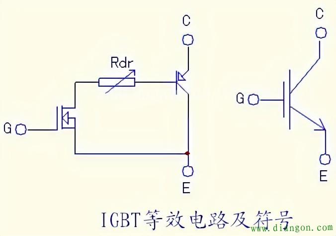
In this article, we talk about the principle, measurement and judgment of IGBT Modules. This article This article only discusses the inverter module made of a single IGBT tube or double tube, and its related measurement and judgment methods. The IPM module is beyond the scope of this article. The field effect tube has the advantages of fast switching speed and voltage control, but also has the disadvantages of large turn-on voltage drop and small voltage and current capacity. Bipolar devices have exactly the opposite characteristics, such as current control, small conduction voltage drop, and large power capacity. The two are compounded, which is the so-called complementary advantages. The origin of IGBT tube or IGBT module is based on this. From the structural point of view, it is similar to the composite amplifier tube that we are all familiar with. The output tube is a PNP transistor, and the excitation tube is a field effect tube. The drain current of the latter forms the base current of the former. The magnification capacity is the product of two tubes.
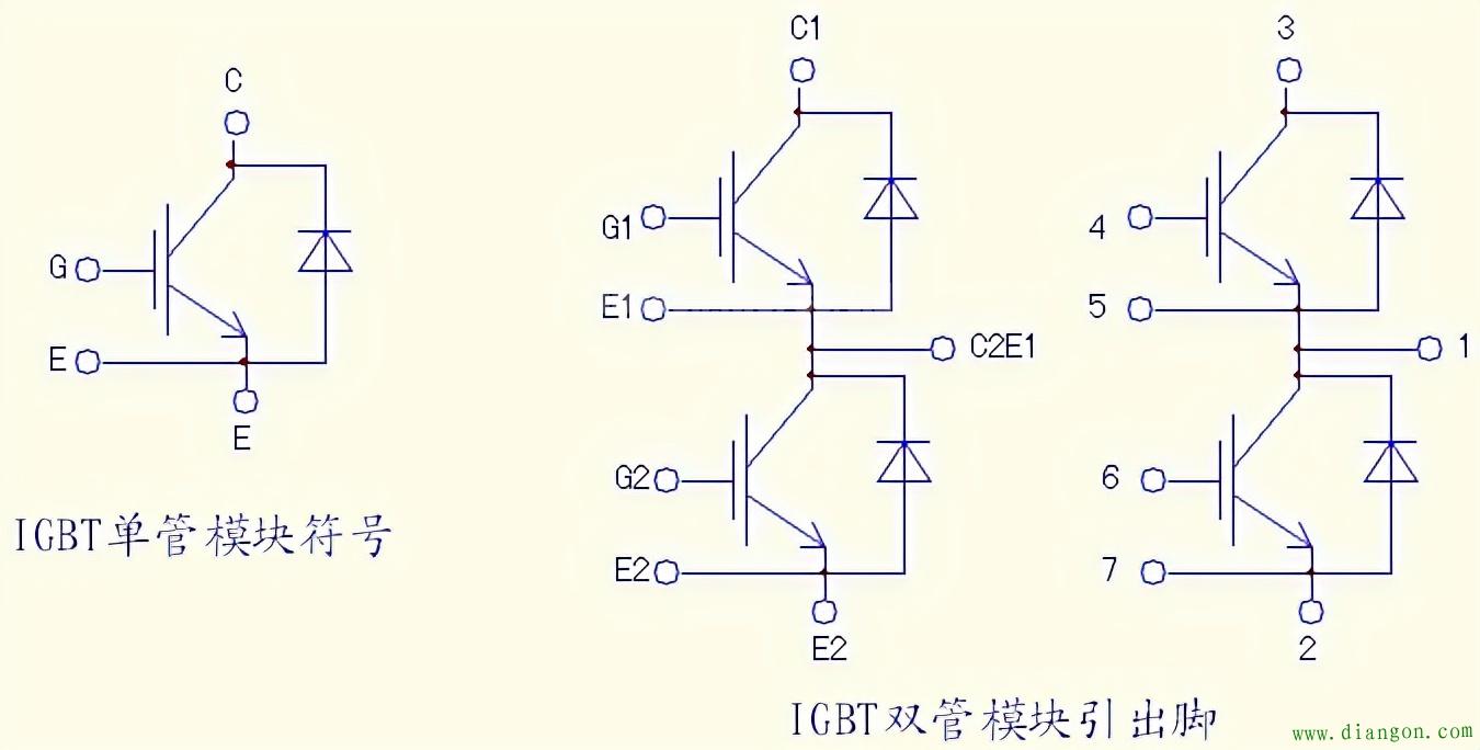
The equivalent Circuit and symbol of the IGBT tube are as follows: The pin function diagrams of commonly used IGBT single and double tube modules (CM200Y-24NF) are as follows:
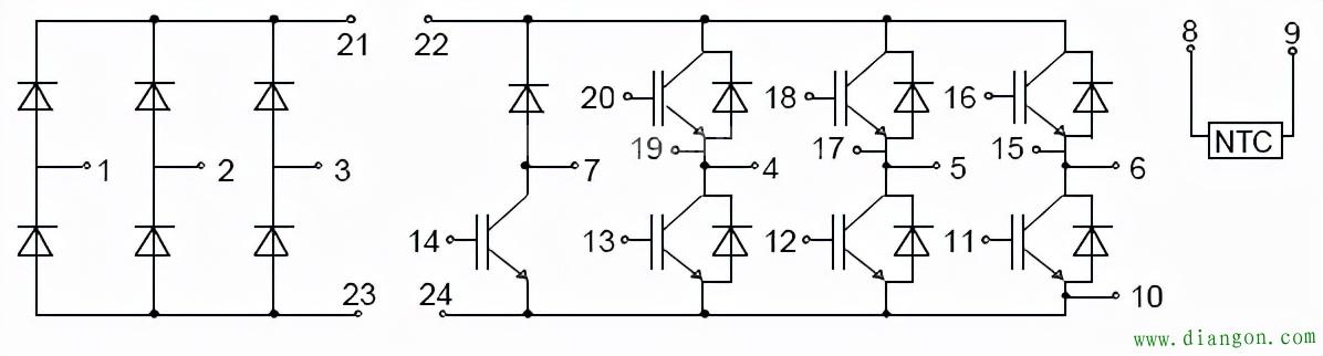
Pin function diagram of FP24R12KE3 integrated module:
Before disassembling the machine, you can roughly measure the quality of the module to make a preliminary judgment. The above figure is an example: Terminals 4, 5, and 6 are the U, V, and W output terminals of the inverter, and 22 and 24 are the P (+) and N (-) terminals of the internal DC main circuit of the inverter. After finding these 5 terminals, you can use a digital or analog multimeter to measure. The U, V, and W terminals all have positive and negative resistance to the P and N terminals. When the IGBT tube is normal, the resistance between tubes C and E is infinite. Only the forward and reverse resistances of 6 diodes connected in parallel on the tube can be measured. If the 4, 5, and 6 terminals are regarded as three-phase AC input terminals, six diodes are equivalent to a three-phase rectifier bridge circuit. It is enough to measure and judge the three-phase rectifier bridge.
1. Online measurement:
1. If the measurement of this “three-phase rectifier bridge” is abnormal, the module is damaged;
2. It is normal to measure this “three-phase rectifier bridge”, and it is still uncertain that the module is good. The main circuit board of the inverter should be opened for further measurement and verification. That is, measure whether the trigger terminal and the internal circuit are normal. Because the trigger terminal is often connected in parallel with a resistance of about 10k (3k in parallel for high-power models), the forward and reverse online resistance of the trigger terminal should be the resistance of the parallel resistance. The resistance values of these 6 trigger terminals should all be the same. If there is a difference in the positive and negative resistance of a trigger terminal, or the resistance becomes smaller, after troubleshooting the drive circuit, the module has been damaged.
3. The resistance measurement of the trigger terminal is also normal. Under normal circumstances, the module is considered to be basically good. But at this time it seems too early to announce that the module is absolutely no problem. See below.
2. Offline measurement:
1. This method is often used for the measurement of high-power single and double modules and newly purchased integrated modules.
After disconnecting the single-tube and dual-tube modules from the circuit (or for newly purchased modules), they can be tested by measuring the field effect tube ( MOSFET) method. There is a junction capacitance between the gate and cathode of the MOSFET, which determines the extremely high input impedance and charge retention function. This feature can be used to effectively detect the quality of the IGBT tube. The method is: set the analog multimeter to the x10k gear, connect the black meter to the C pole, and the red test lead to the E pole. At this time, the measured resistance value is almost infinite; set the test pen and keep it still, and use your fingers to touch the C pole and the G pole. Take it away, the indication is reduced from infinite resistance to about 200k; after tens of seconds or even longer, test the resistance between C and E (the black test pen is still connected to the C pole), and it can still protect the 200k The resistance remains the same; set up the test pen and do not move it, short the G and E poles with your finger, and the resistance between the C and E poles becomes close to infinity again.
In fact, touching C and G with a finger is to charge the gate and cathode capacitor. After the finger is removed, the capacitor has no discharge circuit, so the charge on the capacitor can be maintained for a period of time. The charging voltage on this capacitor is the forward excitation voltage, which causes the IGBT tube to appear slightly turned on, and the resistance between C and E is reduced; when G and E are short-circuited with a finger for the second time, it provides a discharge path for the capacitor. With the discharge of the charge, the excitation voltage of the IGBT disappears, the tube becomes cut off, and the resistance between C and E tends to infinity.
The finger is equivalent to a resistor with a resistance of kΩ, which provides a path for charging and discharging the gate cathode junction capacitance; because the IGBT tube needs a higher forward excitation voltage (above 10V), the x10k file of the multimeter is used , The internal battery power supply of this gear is 9V or 12V to meet the amplitude of the excitation voltage of the IGBT tube.
For the measurement of the trigger terminal, the capacitance can also be measured with a capacitance meter to increase the accuracy of the judgment. Often the module with a large power capacity has a slightly larger capacitance between the two terminals.
2. The following is the data measured by the dual-tube module CM100DU-24H and SKM75GB128DE, and the integrated module FP24R12KE3, using the MF47C pointer multimeter, ×10k file:
CM200Y-24NF module: main terminal C1, C2E1 E2 trigger terminal C1 E1 C2 E2; after triggering, the resistance of C and E is 250k;
The 200nF file of the capacitance meter is used to measure 36.7nF, and the reverse measurement (the black pen is connected to the G terminal, and the red pen is connected to the E terminal) is 50 nF.
The main terminal of SKM75GB128DE is the same as above, the resistance of C and E is 250k after triggering;
Trigger terminal capacitance: 4.1 nF for positive measurement, 12.3 nF for reverse measurement.
FP24R12KE3 integrated module, this method can also be used, after triggering, the resistance of C and E is about 200k;
The trigger terminal capacitance is measured 6.9 nF positively and 10.1 nF reversely measured.
3. Power-on measurement after online measurement or offline measurement can finally determine the quality of the module:
Repair a 37kW TECO inverter and check that the inverter module is damaged, the model is CM100DU-24H. I bought a module of the same type, went through all the “programs” of the offline measurement, confirmed that the module had no problem, installed it and tested it. The three-phase output voltage is very unbalanced. After thoroughly inspecting the drive circuit and confirming that there is no fault, measure the three-phase U, V, W output to the zero line of the three-phase power supply (using a pointer multimeter DC 500V gear), U-phase, W-phase DC The composition is zero. The V phase has a DC negative voltage of about 300V. Judging from this: the V phase lower tube conduction is good, but the upper tube conduction is poor, causing V to have a negative voltage output relative to the neutral line. The V-phase upper tube happens to be a newly replaced module. After purchasing another CM100DU-24H and replacing it, the three-phase output is normal. The failure of the tube is that the internal MOSEFT tube is normal, so online or offline measurement is normal. The internal resistance between the C and E poles of the internal output tube becomes larger. It shows one thing, even if it is considered a good inverter module after careful measurement, it cannot be 100% determined that there is no problem. After all, the measurement and judgment ability of a multimeter is limited. Regarding the problems reflected after the access circuit is powered on, do not have preconceived ideas, thinking that the module cannot be broken, which will cause false disconnection of the fault and lead the maintenance into a detour!
|