

Content last revised on September 22, 2026
Incoming Benchtop Inspection: LCD Panel and Connector Integrity
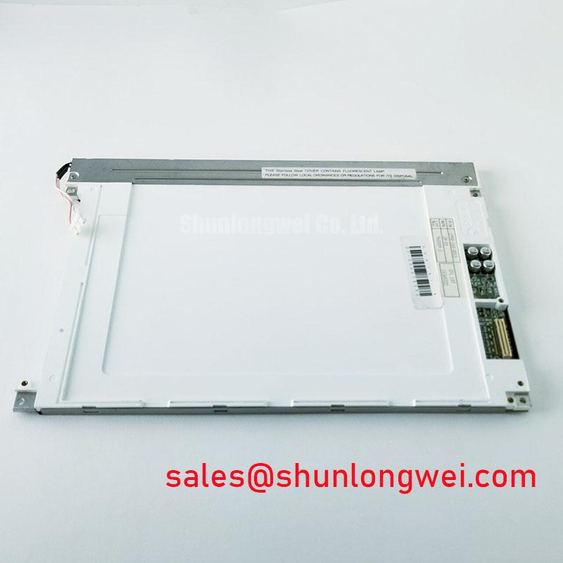
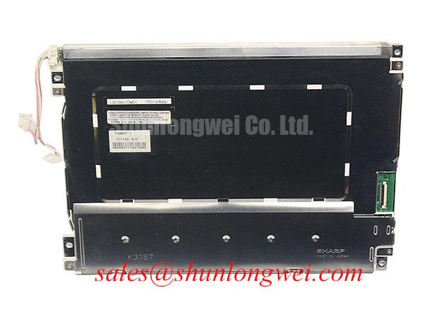
Begin incoming inspection by placing the LQ104V1DW01 on an ESD controlled bench, checking the TFT LCD display module frame, viewing area, connector condition, and cable contact surfaces before applying power. This Sharp panel is identified as an Industrial Grade LCD/HMI Panel. The original equipment documentation should remain the authority for electrical limits, interface assignment, backlight requirements, and mechanical fit.
Use a controlled full screen red, green, blue, black, and white test sequence when the original host board or a documented compatible controller is available. Solid primary colors can reveal permanently illuminated pixels, dark pixels, column irregularities, local color shifts, line artifacts, and nonuniform image regions that may not be apparent on a normal operating screen. A full black screen is particularly useful for observing unwanted light leakage around the visible perimeter, while a white image makes luminance variation easier to compare across the active area.
For a dark shadow check, inspect the display at an oblique angle with an external flashlight while the module is unpowered. This can help identify surface marks, glass stress indications, frame pressure points, or contamination around the bezel. It does not prove an internal fault mechanism. Any observed horizontal or vertical line should be compared with a known good signal source, the original cable, and the mating connector before attributing the condition to the panel.
💡 Bench Tip: Disconnect system power before inserting or removing the display cable, and keep the connector fully aligned before engaging its lock to avoid contact damage or uneven pin engagement.
Connector inspection should focus on practical contact reliability. Check whether the cable is seated evenly across its full width, whether the locking feature is correctly engaged, and whether the connector housing shows distortion. A display that intermittently changes image quality when the cable is lightly stabilized may indicate a connection path issue, but the panel, cable, controller, and supply rails should all be verified as part of the same test path.
Cold ambient operation can alter liquid crystal response behavior and make transitions appear slower than at room temperature. This is a Design Consideration, not an official temperature performance claim for the LQ104V1DW01. Where equipment operates in low temperature environments, system engineers should test actual image refresh behavior, contrast stability, and start up performance against the requirements of the original equipment.
When a replacement assessment is required, physical dimensions, mounting points, visible area, interface type, connector orientation, supply requirements, and timing compatibility all require confirmation. The LMS700KF01-001 can be reviewed as a separate display option during a documented replacement evaluation, but it should not be treated as a direct interchange without verifying the complete host system interface and mechanical conditions.
Backlight Rail Thermal Dissipation and Optical Uniformity Assessment
The official product description identifies the LQ104V1DW01 as a Sharp TFT LCD Display Module, but the supplied factory data does not confirm its backlight construction, luminance rating, optical coating, light guide material, or operating lifetime. Those characteristics should therefore be confirmed from the original panel documentation or the equipment manufacturer’s service information before selecting a backlight driver, modifying the enclosure, or establishing a brightness target.
During bench operation, allow the panel to reach normal equipment operating conditions and compare screen uniformity using full white, gray, and black images. Inspect for localized bright zones, dark regions, edge glow, changing color appearance, or brightness movement after warm up. These observations support maintenance decisions, although they do not alone identify a single failed part. The backlight assembly, thermal path, driver circuit, controller settings, diffuser condition, and enclosure ventilation can all influence the visual result.
Heat management around a display module is a Design Consideration. Where the system includes narrow mechanical clearances or a sealed front enclosure, installers should preserve the original thermal contact arrangement and avoid creating pressure on the panel frame. The system engineer should verify thermal behavior under the actual duty cycle, ambient conditions, display brightness setting, and enclosure configuration. Thermal changes introduced during repair should be evaluated with the display fully assembled, because an open bench condition may not reproduce installed heat flow.
Direct sunlight can reduce perceived display contrast even when a panel functions correctly. For outdoor facing equipment or a navigation console near bright windows, the suitability of the complete display assembly depends on the original enclosure, front filter, mechanical shading, user viewing angle, and environmental sealing. The LQ104V1DW01 should be evaluated within that assembled system rather than assigned an unsupported sunlight readability rating.
A separate display device such as LQ9D03B may be relevant when reviewing related display assemblies or supporting hardware, but the power architecture of the original equipment must determine whether it has any functional relationship to this Sharp panel. Do not transfer supply or backlight assumptions from one module to another without confirmed documentation.
For broader maintenance planning, The Ultimate Guide to Industrial TFT LCD Technology provides engineering context on industrial TFT LCD selection and common integration checks. For this specific model, verified model level documentation remains necessary before drawing conclusions about optics, backlighting, environmental behavior, or mechanical protection.
Logic Supply and Display Interface Verification Before Power Up
Before connecting the LQ104V1DW01 to a controller, compare the panel label and original equipment records with the host board connector designation. The supplied official data confirms the product category and module format, but it does not specify the required logic supply voltage, connector pinout, signaling standard, data mapping, resolution, timing values, or power sequencing. The system integrator should verify these requirements from the original panel documentation.
Do not assume that a display module uses a particular logic rail or interface simply because another panel of similar size appears visually compatible. TFT LCD modules can differ in connector position, panel timing, differential or parallel data format, enable behavior, backlight control arrangement, and image mapping. An apparently powered display can still show a blank image, corrupted colors, split screen behavior, unstable synchronization, or intermittent operation when the host interface does not match the documented requirements.
A controlled replacement check normally starts with the original cable and original host controller. Inspect cable folding paths, strain relief, locking direction, and connector seating before considering changes to firmware or timing settings. If waveform analysis is available, compare the suspect signal path against a known good equipment path using appropriate probes and measurement practice. This is an Engineering Recommendation intended to isolate the interface path without assigning unsupported electrical limits to the LQ104V1DW01.
Power sequencing is also system determined. The controller, panel logic supply, and any illumination circuit should be energized and disabled according to the original equipment documentation. A repair technician should avoid connecting an undocumented power source directly to the module connector. If the equipment uses a separate display controller or timing board, its supply stability and control signals should be inspected alongside the display module.
| Verification Area | Check Before Installation | Classification |
|---|---|---|
| Panel Identity | Confirm the label reads LQ104V1DW01 and manufacturer marking is Sharp. | Official product identification |
| Product Format | Confirm the replacement requirement is for a TFT LCD Display Module. | Official factory specification |
| Interface Connection | Verify connector type, pin assignment, cable orientation, and locking method from original documentation. | Engineering recommendation |
| Supply Requirements | Verify the required supply voltage and sequencing from the original panel documentation. | System determined |
| Image Test | Run primary color, grayscale, black, and white test images through a known good signal path. | Engineering recommendation |
For equipment repair work, retaining the documented original cable and controller configuration reduces uncertainty. If replacement cabling is unavoidable, the installer should verify its conductor arrangement, shielding approach, mechanical retention, and electrical suitability through system level testing rather than visual similarity alone.
Backlight Driver Compatibility, Dimming Behavior, and Flicker Checks
The LQ104V1DW01 should only be connected to a backlight supply arrangement confirmed by its original documentation or the original host equipment. The available factory data does not establish whether the module uses a specific illumination technology, input voltage, current requirement, dimming method, or lamp driver architecture. It is therefore inappropriate to assign a CCFL or LED configuration to this model without confirmed source information.
When the original system powers the display but the image is weak, unstable, or intermittently visible, separate the diagnosis into display data, logic supply, backlight control, and illumination power paths. A dim image can arise from more than one condition. Verify the controller output, panel enable state, cable connection, driver behavior, and original system settings before replacing parts. If the image changes after the system warms up, observe whether the change follows the panel, driver, cable, or controller when tested against known good equipment.
Flicker evaluation should be performed with the screen showing a stable image at the brightness setting used in service. Observe the panel directly and, where appropriate, use measurement equipment suitable for the suspected control signal or illumination path. A camera alone can introduce shutter related artifacts, so it should not be treated as definitive evidence of display flicker. The relevant objective is to determine whether the behavior remains present when the panel is operated through a verified host path.
Brightness adjustment and dimming behavior are controlled by the complete equipment design. This is a Design Consideration for industrial HMI maintenance. Technicians should preserve the original control wiring, display controller configuration, and enclosure arrangement whenever practical, then validate operation through repeated start up, stable image display, and normal control response tests.
For potential use in marine radar and navigation bridge console repair, the LQ104V1DW01 should be assessed as a replacement display module only after confirming the original console’s electrical interface, front enclosure sealing, cable routing, optical requirements, and environmental maintenance procedures. Its documented identity as a Sharp industrial grade TFT LCD/HMI panel supports a focused replacement review, while final compatibility remains dependent on the equipment level design.