

Content last revised on September 10, 2026
Sharp LQ10D363 Replacement Verification
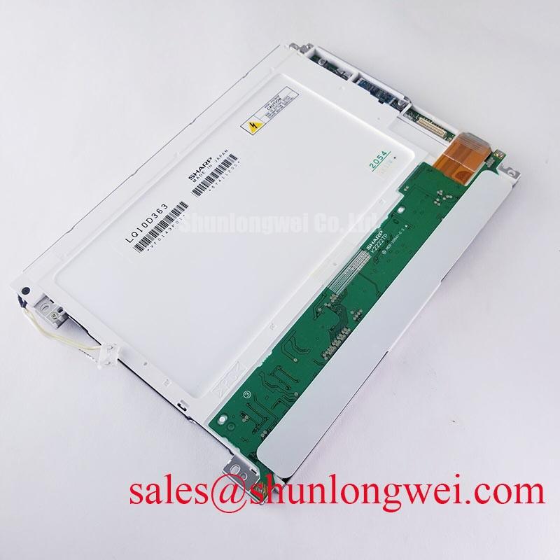
Check the Sharp LQ10D363 against the removed display before installation by confirming the nameplate, connector position, panel outline, and original equipment documentation. The available factory information identifies it as an Industrial Grade LCD/HMI Panel in a TFT LCD Display Module format, with its specification status recorded as Official Factory Spec Verified. Electrical interface details, optical ratings, dimensions, backlight construction, and touch configuration should be verified from the original panel documentation before a replacement is energized.
This approach is especially important when the display is being evaluated for a hazardous petrochemical Zone 2 explosion-proof operator station or a field monitoring terminal. The enclosure may provide the hazardous-area protection, while the LCD module remains one part of the complete system. The LQ10D363 itself should not be treated as an independent explosion-proof assembly, EMC-certified system, or safety-certified control unit unless the complete equipment documentation states otherwise.
Aluminum Heat Spreader Sizing & Thermal Interface Placement along Narrow Display Edges
During inspection, look for uneven contact between the display frame, heat-spreader rails, and the enclosure. Narrow metal edges can create localized thermal paths, so the mechanical interface should distribute pressure and heat without loading one corner of the TFT module. An aluminum rail may be evaluated as a general thermal design measure where the system produces heat near the display edge, but the rail dimensions, attachment method, and thermal interface material remain system-dependent. They should be selected after measuring the enclosure, the display frame, nearby electronics, and the available airflow path.
The purpose of the spreader is to reduce local temperature concentration rather than to claim a specific panel temperature limit. Designers should verify the result with temperature measurements taken at several points around the bezel and rear surface during the intended operating cycle. A single central measurement can miss an edge hot spot caused by a driver board, a backlight converter, or restricted cabinet airflow. The display supplier’s mechanical drawing and the original equipment service documentation should control all keep-out areas and mounting references.
Optical ageing claims also require care. The supplied factory information does not establish a guaranteed PMMA light-guide composition, LED lifetime curve, L70 value, B50 value, or a panel-specific thermal life model for the LQ10D363. Those figures should not be assigned to this model without a manufacturer datasheet or test report. A design review can still assess the risk of yellowing, brightness non-uniformity, or reduced backlight output by comparing measured temperatures and luminance against the equipment’s known-good display.
For the video path, identify whether the host system uses TTL or LVDS before connecting a replacement. The physical presence of a similar connector does not prove compatible logic levels, pin assignment, channel order, or timing. Clock stability, data hold time, and transmitter jitter should be checked across the actual industrial temperature window selected by the equipment designer. If the display image is stable at room temperature but develops intermittent lines after cabinet heating, compare the clock and data waveforms with a known-good unit rather than assigning the fault to the panel alone.
A practical evaluation can begin with power removed: inspect connector pins, check for contamination, document cable routing, and compare the display’s rear markings with the original service record. After controlled energization, monitor the supply at the panel connector while the host changes brightness and image content. This can help separate a display-interface issue from a power-distribution or controller problem. The LQ10D363 product category is confirmed as a TFT-LCD display module; the system integrator should verify the required supply voltage from the original panel documentation.
For broader enclosure and display integration practices, engineers can consult the Industrial Display & HMI Solutions reference material. It can be used as a general engineering resource and does not replace the original Sharp documentation for this model.
VESA vs. JEIDA Data Mapping Alignment & Even/Odd Channel Signal Integrity
Before changing a controller board or cable, record the existing image topology. The LQ10D363 should be connected only after the integrator confirms the interface family, data mapping, channel arrangement, connector keying, and power-sequencing requirements. JEIDA and VESA mapping are not interchangeable assumptions. A mismatch can produce colour errors, misplaced pixels, split-screen effects, or an image that appears active but is electrically misaligned.
High-speed display links should be routed as controlled differential pairs where the host interface requires them. A 100 Ω differential characteristic impedance is a general Design Consideration for many LVDS links, not an official LQ10D363 rating unless it is stated in the applicable Sharp interface documentation. The PCB stack-up, connector transition, cable construction, return path, and termination strategy all affect the actual result. Engineers should verify the complete channel with the intended cable and controller rather than checking only the board trace.
Skew between even and odd data channels can reduce the timing margin available to the receiver. The appropriate skew budget is determined by the controller, panel receiver, pixel clock, cable length, and environmental noise. A value such as 50 ps may appear in a system design target, but it must not be presented as a factory limit for the LQ10D363 without a supporting datasheet. Oscilloscope measurements should be made at the receiver-side interface when possible, with probing methods that do not substantially disturb the differential pair.
Power-on behaviour deserves the same attention. The host should follow the sequence specified by the original display documentation for logic supply, enable signals, reset functions, and backlight control. The project brief references a possible rise-time window of 0.5 ms to 10 ms, but this is a system integration checkpoint rather than a confirmed LQ10D363 factory specification. Designers should verify the required sequence from the original panel documentation and then test repeated cold starts, warm restarts, brownout recovery, and controller resets.
In a factory cabinet, servo drives, contactors, switching supplies, and motor cables can introduce common-mode noise into the display harness. Keep the display cable separated from high-current switching conductors where the enclosure permits, maintain a deliberate return path, and review shield termination according to the cabinet EMC strategy. The display module cannot independently claim compliance with CISPR, EN 55011, or any complete equipment EMC certification. Compliance belongs to the assembled product and its verified installation conditions.
When a replacement produces intermittent vertical bands, colour changes, or half-screen activity, inspect the connector seating and cable bend first, then compare supply stability and clock/data waveforms with the original unit. These symptoms may indicate mapping mismatch, impedance discontinuity, connector contact variation, or host timing instability. A diagnostic conclusion should be based on measured signal behaviour and the known-good signal path rather than on the visual symptom alone.
The LM190E08-TLG6 may be reviewed as a separate reference display during same-class or same-resolution compatibility work. It is not a substitute recommendation for the LQ10D363. Any comparison must confirm active area, resolution, interface, mechanical outline, mounting points, backlight control, and the host controller’s supported timing.
Surface Anti-Glare (AG) & Anti-Reflective (AR) Etched Coating for High Ambient Readability
Inspect the front surface under the actual lighting conditions in which the operator station will be used. Reflections from cabinet windows, overhead fixtures, status lamps, and protective glazing can reduce readability even when the panel is electrically healthy. The available factory data does not confirm a specific AG coating, AR treatment, haze value, surface hardness, viewing angle, or touch-surface construction for the LQ10D363. These characteristics must be verified from the panel documentation or by evaluating the actual unit.
AG and AR are different optical approaches. A textured anti-glare surface scatters reflected light, while an anti-reflective treatment is intended to reduce reflection at the surface. The final result depends on the cover window, air gap, bonding method, ambient illumination, viewing position, and display brightness. A highly diffuse surface may reduce mirror-like reflections but can also affect perceived sharpness. Designers should assess the complete front stack rather than selecting a coating based on a catalogue label alone.
TN, IPS, and MVA are also not interchangeable descriptions. The factory information supplied for this page does not confirm the LQ10D363 panel mode or a symmetric viewing specification such as 85° in all four directions. Viewing performance should therefore be measured or confirmed from the original optical datasheet. When an operator moves vertically or horizontally, check grayscale stability, contrast change, colour shift, and possible inversion at the intended viewing angle.
Low-temperature operation can alter liquid-crystal response and may lengthen visible transitions. That observation is a general Design Consideration, not a stated LQ10D363 response-time guarantee. If the display is used in an unheated outdoor cabinet or a cold process area, the integrator should evaluate the actual start-up sequence, image response, condensation risk, and enclosure temperature. A heater strip may be considered only as part of the complete environmental control design, with its location and control logic validated against the panel’s permitted operating conditions.
Condensation deserves a physical inspection during service. Look for moisture near the bezel, connector, cable entry, and protective window after a cold-to-warm transition. The enclosure’s sealing, pressure equalization, drain path, and internal heat sources influence the result. The LCD module should not be credited with an ingress-protection rating unless the assembled equipment has been tested and documented to that rating.
⚠️ Maintenance Note: Check the cabinet airflow path and the condition of the sealing gasket during scheduled maintenance, because dust or a displaced gasket can affect both thermal behaviour and optical readability.
Thermal Expansion Clearance Sizing across Heavy Industrial Metal Enclosure Cutouts
Remove the display bezel or front frame only according to the equipment service procedure, then document how the module is supported before loosening fasteners. Heavy industrial cutouts can transmit distortion into a thin display assembly when the surrounding metal expands, contracts, or is tightened unevenly. The LQ10D363 product description confirms a TFT-LCD Display Module, but the supplied factory information does not provide an outer bezel envelope, mounting-hole drawing, clearance tolerance, or approved fastener torque.
For that reason, the enclosure designer should obtain the original mechanical drawing before machining a replacement cutout. Verify visible area, rear clearance, connector access, cable bend space, bezel overlap, and the position of every mounting point. Clearance should accommodate the measured assembly and the enclosure’s expansion behaviour without allowing the panel to move excessively. The correct allowance is determined by the materials, temperature range, fastener pattern, gasket construction, and installation method.
Cross-pattern tightening is a useful general installation method because it helps distribute load, but the permitted torque must come from the display or equipment manufacturer. The proposed 0.35 to 0.45 N·m range is not an official LQ10D363 specification in the supplied data and should not be applied without confirmation. Use a calibrated tool when the service manual defines a torque, and verify that washers, spacers, gasket compression, and screw length match the original assembly.
After installation, inspect the display with a uniform dark image and then with a bright field. Look for pressure marks, corner shadows, uneven luminance, or local changes that appear only after the fasteners are tightened. These observations can indicate mechanical loading, frame distortion, cable interference, or a pre-existing optical condition. Release and retighten the mounting hardware only under the approved service procedure; do not attempt to correct a visible artefact by increasing clamping force.
Backlight troubleshooting should begin at the system boundary. Confirm the host’s backlight enable signal, inspect the cable and connector, and measure the driver output using a method suitable for the circuit. An open or short indication may originate in the driver, wiring, protection circuit, or display-side backlight assembly. The available LQ10D363 information does not confirm an LED string arrangement, open-load threshold, short-circuit threshold, rated current, or backlight lifetime. Those values must be taken from the applicable electrical documentation rather than inferred from the panel category.
Brightness decline should be recorded against the equipment’s operating history and measured under repeatable conditions. A statement such as 50,000 hours to 50 percent brightness is not an official LQ10D363 lifetime rating in the supplied factory data. LED lifetime depends on drive current, thermal conditions, duty cycle, optical configuration, and driver regulation. Engineers evaluating constant-current operation should compare luminance and temperature at defined maintenance intervals, while keeping field observations separate from manufacturer qualification data.
For a Zone 2 operator station, final acceptance should include the complete enclosure, window, touch interface if fitted, cable glands, power supply, controller, and protective earth arrangement. The LQ10D363 can be evaluated as an industrial LCD/HMI panel within that assembly, but the complete station remains responsible for hazardous-area, electrical safety, environmental, and EMC compliance. The original panel documentation should govern every unconfirmed electrical, optical, and mechanical value before the equipment returns to service.