



Content last revised on September 27, 2026
Benchtop Waveform Tuning: Mitigating Stress via High-Current DC Rectifier Topologies for MDC350-5
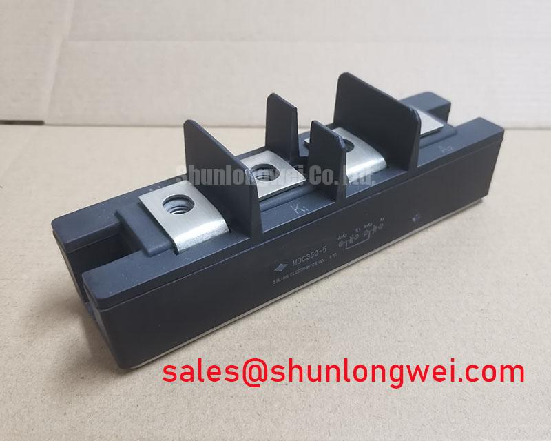
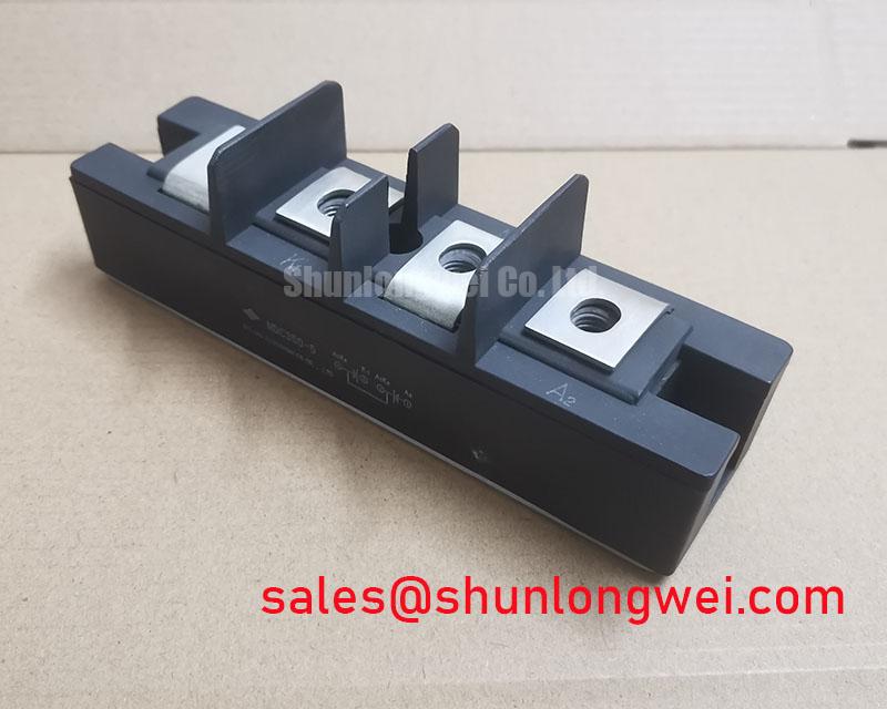
For a high-current green hydrogen electrolyzer DC power rectifier, begin the bench evaluation by identifying whether the failed position belongs to a six-pulse or twelve-pulse bridge. The MDC350-5 is a dual diode module, so it should be assessed as part of the complete rectifier topology rather than as an isolated switching device. In a six-pulse arrangement, phase-leg current sharing, transformer leakage, commutation overlap, and busbar symmetry directly affect the electrical stress seen by each diode path. A twelve-pulse arrangement adds an interphase transformer or equivalent phase-shifting structure, making current balance between rectifier groups a primary commissioning check.
Use the module’s 350.0 A rating as an official product reference, not as a substitute for the system’s permissible RMS current, surge-current limit, thermal operating point, or overload profile. Those values depend on the complete heat sink, airflow or liquid-cooling arrangement, duty cycle, transformer impedance, and protection network. During waveform capture, compare the current in parallel paths and inspect the commutation interval for abnormal recovery spikes. If one branch carries visibly different current, check busbar geometry, transformer phase relationships, connection resistance, and the condition of the other semiconductor positions before attributing the issue to this module.
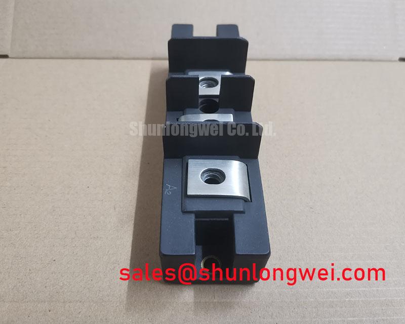
Fuse coordination must be verified from the applicable IXYS documentation and the selected semiconductor fuse manufacturer’s I²t data. No fuse I²t coordination table is provided in the product information supplied for this page, so a specific fuse part number or clearing-energy claim would be inappropriate. The protection study should compare the fuse clearing characteristic with the diode’s published surge and short-circuit withstand data under the actual prospective fault current. The engineer responsible for the rectifier should also verify whether the module’s SOT-227B or TO-240AA mounting arrangement matches the existing busbar and heat-sink hardware.
For topology references, engineers evaluating adjacent high-current rectifier positions may also review SKN320-04 as a separate product reference. It should not be treated as an automatic substitute; voltage class, current waveform, package geometry, thermal interface, and protection coordination must all be checked independently.
Field Diagnostics & Commissioning: Preventing Localized Stress in MDC350-5 Topologies
Although the supplied commissioning outline mentions gate firing pulses and gate-hotspot behavior, the MDC350-5 is identified here as a dual diode module. It does not provide a gate terminal in the manner of an IGBT or thyristor module. Gate pulse rise time, back-porch holding current, Miller charge, active gate clamping, and gate-loop damping therefore belong to an upstream controlled device or firing assembly, not to the diode module itself. Keeping this distinction clear prevents technicians from applying an unsuitable gate-drive test to a passive rectifier position.
For field diagnosis, isolate the DC link and discharge the energy-storage section according to the equipment service procedure. Record the module location, polarity orientation, busbar arrangement, and cable routing before removal. A cold resistance comparison can help identify an obvious shorted junction or an open connection, but a static meter result is not a complete semiconductor health assessment. Temperature, stored charge, parallel circuit paths, meter polarity, and connected snubber components can influence the reading. If the result is inconsistent with a known-good position, remove the surrounding parallel paths from the measurement and confirm the result with an approved semiconductor test method.
During commissioning, examine the AC-side phase currents and the rectified DC waveform under controlled load. Uneven phase current can arise from transformer imbalance, loose power connections, unequal thermal conditions, a damaged companion diode, or measurement-probe placement. Oscilloscope probes and current sensors should be rated for the actual common-mode and transient environment. Industrial isolation and probe connection procedures remain the responsibility of the test engineer.
Power-quality assessment should include displacement and distortion effects where the rectifier is connected to a substantial transformer or utility supply. The general concept of total harmonic distortion can be reviewed in the reference article on Total Harmonic Distortion in Power Quality Engineering. That reference does not establish a product-specific limit for the MDC350-5, so measured harmonic performance must be evaluated against the equipment specification and the applicable installation requirements.
MDC350-5 Operational Boundaries: Evaluating Short-Circuit Withstand and Protection Coordination Limits
A dead-short study for the MDC350-5 requires more than matching a fuse current label with the module’s 350.0 A rating. The relevant comparison includes prospective fault current, fuse melting and clearing I²t, diode surge capability, source impedance, busbar inductance, transformer impedance, and the physical location of the protective device. Because the official product data supplied here does not include a fuse coordination table or a published I²t value, no guaranteed zero-damage short-circuit conclusion can be made.
In practice, the service engineer should collect the original rectifier schematic, identify every parallel current path, and determine whether the fuse protects an individual module, a bridge group, or the complete DC output. The fuse manufacturer’s time-current and I²t curves should then be checked against the semiconductor manufacturer’s limits at the actual prospective current. A fuse that interrupts the fault quickly may still allow damaging current sharing through adjacent paths if the physical layout creates unequal impedance.
Inspect the module terminals and busbar interfaces for localized discoloration, loosened hardware, oxidation, or evidence of repeated thermal cycling. These findings do not prove the failure mechanism by themselves, but they justify a wider inspection of the bridge, transformer secondary, snubber network, and cooling assembly. After replacement, energization should proceed through the equipment’s approved precharge and current-limited test method, with DC voltage, phase current, diode temperature, and abnormal acoustic or electrical behavior monitored.
Long-duration power-conversion evaluation also benefits from a system-level view of efficiency, modular architecture, service access, and thermal distribution. The technical discussion in The Race for Efficiency provides broader context for high-power modular converters, but it does not replace the MDC350-5 manufacturer’s electrical and thermal limits.
Transient Dynamics & Electrical Design: Mechanical Mounting Torque Sequence and Thermal Contact
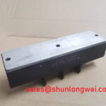
The SOT-227B / TO-240AA package places the mechanical interface directly inside the thermal and electrical path. Before fitting an MDC350-5, clean the heat-sink contact surface, remove old interface residue, and verify that the mounting plane is free from burrs or distortion. The product information supplied does not state a model-specific mounting torque, so the installation team should follow the applicable IXYS mechanical instructions and the fastener manufacturer’s requirements rather than apply an assumed value.
Apply the thermal interface material evenly and avoid conditions that can tilt the module or leave unsupported areas beneath the base. Tighten the mounting hardware progressively in the specified sequence, checking that the package remains seated while the pressure is distributed across the intended contact region. Excessive or uneven force can deform the package or worsen thermal contact; insufficient force can increase interface resistance and produce a temperature difference between parallel rectifier positions.
⚠️ Field Alert: Disconnect and verify the absence of stored DC energy before touching the module terminals, and never insert or remove power connections while the rectifier is energized.
After installation, confirm terminal alignment, polarity, busbar clearance, and cable strain relief before applying power. Minimize parasitic inductance in the high-current commutation loop to reduce turn-off overshoot, but determine the acceptable transient margin from the complete system voltage, layout, measurement results, and semiconductor ratings. The same principle applies to snubber placement: locate the network according to the actual current loop and validate its effect with appropriately rated differential and current probes.
Thermal verification should compare temperatures across equivalent diode positions during the intended operating duty. A difference between branches may indicate unequal current sharing, interface variation, cooling imbalance, or an upstream circuit condition. The result should be assessed together with waveform and current measurements rather than assigned to one cause in isolation. The MDC350-5 package and 350.0 A official current rating provide the product identity baseline; the final operating boundary remains dependent on the complete rectifier assembly and its verified thermal design.