



Content last revised on September 30, 2026
Aluminum Heat Spreader Sizing & Thermal Interface Placement along Narrow Display Edges
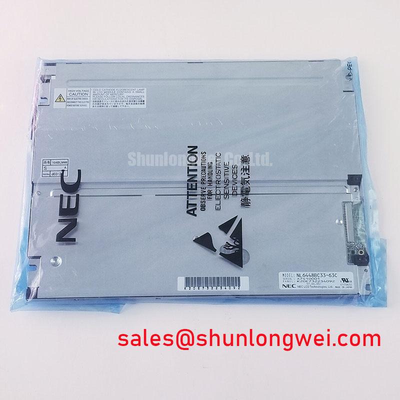
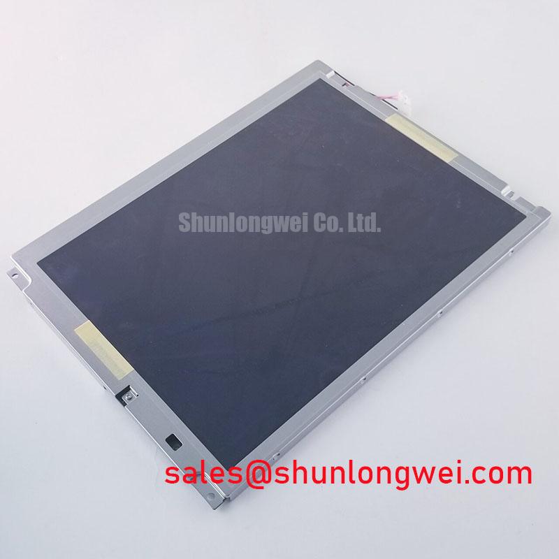
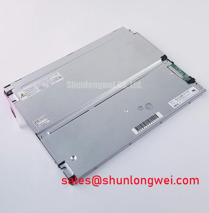
Check the installed panel’s narrow edges for concentrated heat, frame contact and uneven pressure before changing its thermal mounting. On a dark or uneven display, compare edge temperatures while the unit runs its normal image pattern, then inspect whether nearby electronics or enclosure parts are heating the frame. A hot edge does not, by itself, identify a failed NL6448BC33-63C; the heat source may sit elsewhere in the assembly.
An aluminum spreader rail is a Design Consideration, not a specified part of this NEC module. If the enclosure needs one, the mechanical designer should establish its contact area and thermal path without loading the display glass, cable exit or connector. Evaluate the assembled unit under its actual duty cycle and ambient conditions. Do not assume a rail will protect a particular optical material or deliver a stated backlight lifetime: neither the internal material stack nor a lifetime rating is established by the supplied factory parameters.
For a cold-start complaint, record the ambient temperature, panel image and elapsed time from power-up. Liquid-crystal response can slow as temperature falls, but no sub-zero operating limit, gray-to-gray response figure or heater-strip requirement is established here. If the host equipment uses a heater, check its control against the equipment documentation and observe the complete display assembly during warm-up. The system engineer should set the permitted operating conditions from the original panel and enclosure specifications rather than treating a generic industrial temperature range as an NEC rating. The industrial TFT LCD technology guide provides context for separating panel behavior from enclosure-level thermal design; Tianma’s industrial display information is a separate industry reference, not a specification for this NEC model.
Flashlight Dark-Shadow Optical Diagnostic to Isolate Logic vs. Backlight Failure Modes
Shine a flashlight across the dark screen at an oblique angle while the host sends a known image. If a faint image is visible, investigate the illumination supply and its control path; if no image is visible, continue checking both image-signal delivery and illumination rather than declaring the panel logic defective. Repeat the observation with the display viewed from more than one position, since reflections can hide weak image detail.
For bench isolation, display full-field red, green and blue patterns from a known-good host configuration and note whether missing regions, fixed lines or color errors remain in the same positions. The patterns are diagnostic inputs, not proof of a particular driver construction or failure mechanism. Compare the suspect screen with a known-good signal path when one is available. Reseat and inspect the external display connector only after isolating power, paying attention to latch engagement, contact contamination and cable strain at the exit point.
Field Alert: Disconnect power before unplugging or reseating the display cable.
At the connector, measure the panel supply and observe whether image timing is present through start-up and shutdown. Engineering Recommendation: use the host schematic and original panel documentation to identify the required voltage, connector pinout, signal format and sequencing; do not infer them from the NL6448BC33-63C model name. Probe timing at the receiving connector where practical, because a waveform that looks sound at the transmitter may be degraded by the cable or contact interface. Clock-jitter and data-hold limits must come from the documented interface before a measured waveform can be judged against a numeric margin.
A white screen or a retained image during power-down also calls for a sequence check. Capture supply, image-enable and illumination-control behavior on the installed system and compare it with the equipment’s intended sequence. Separate a persistent panel defect from a host that continues driving signals while a supply collapses. The same method applies when an HMI holds a static image for long periods: first determine whether the apparent afterimage clears with a changing test pattern, then assess the complete system’s display settings without assigning an unsupported retention or service-life figure to this panel.
Suppressing Pixel Jitter & Horizontal White Lines Induced by Adjacent 400V Motor Drives
Capture the display fault with the nearby motor drive running and stopped, then compare the panel supply and image-signal waveforms at the receiving connector. Correlation with drive operation makes interference worth investigating; it does not establish that the drive is the sole cause. Record whether the disturbance changes with cable position, connector movement or illumination state before altering the installation.
Design Consideration: inspect the existing cable shield termination and its route relative to the motor wiring when jitter or horizontal bands appear. Grounding arrangements and ferrite selection belong to the host’s electrical design. A shielded cable or common-mode ferrite may be evaluated under the system’s grounding scheme, but neither is a guaranteed cure, and no specific cable construction or interface type is established for NL6448BC33-63C. Test any change at the panel connector with the drive operating over the conditions that produced the fault.
Check supply integrity as well as data quality. If the image disturbance tracks a dip or ripple on the panel supply, trace that supply through its connectors and power distribution before changing the signal cable. If the supply stays stable, compare the clock and data behavior with the host interface requirements, including start-up and temperature-dependent cases relevant to the equipment. An oscilloscope observation can narrow the fault location; it cannot replace the original timing limits.
Glare is a separate visibility problem. Observe the installed display from the operator’s normal position under the lighting that triggers the complaint, and distinguish reflected light from electronically generated white bands. No direct-sunlight contrast ratio or anti-glare surface treatment is established by the supplied factory parameters. For a railway passenger-information terminal or cab-signalling display being assessed as a potential application, the integrator should verify sunlight legibility, enclosure suitability and interface compatibility at the equipment level. Such an application example does not establish railway approval or suitability for this panel.
Grayscale Inversion Mitigation & Optimal Viewing Direction Alignment
Move the viewing position through the equipment’s expected operator angles while showing a grayscale ramp and the actual HMI screens. Note where dark steps merge, colors shift or symbols lose contrast. Do not attribute a viewing-angle complaint to TN grayscale inversion until the optical mode and specified viewing direction of NL6448BC33-63C have been established from its original panel documentation; those details are not present in the supplied factory parameters.
Check mounting orientation against the documented preferred viewing direction before changing the interface artwork. A panel can appear acceptable straight on yet make a critical low-contrast symbol difficult to read from the operator’s seat. Engineering Recommendation: evaluate the assembled HMI with its cover lens, lighting and normal viewing positions in place. If the equipment team is considering optical bonding or a surface treatment, test the finished stack for readability and service access; do not assume this NEC module is bonded, sealed or supplied with an anti-glare finish. Industrial display product information from NEC offers manufacturer context, but the model’s optical limits must come from its applicable specification.
If a wider-viewing alternative is being evaluated, compare its mechanical envelope, connector pinout, supply, image timing, viewing characteristics and illumination arrangement as separate requirements. IPS or MVA viewing behavior cannot be assigned to this panel without evidence, and a different NEC model is not a drop-in replacement on the strength of its display category alone. The NL8060BC31-41D comparison can support a broader specification review, but compatibility with NL6448BC33-63C requires an item-by-item check against the equipment design.
When an apparent viewing-angle fault changes during connector movement or a cold start, return to the electrical checks rather than compensating with mounting angle alone. Verify that the flexible cable is not held under strain, that its connector remains locked and that the received image timing stays stable through the operating conditions being assessed. Those observations separate an optical limitation from an intermittent signal path without assigning an unverified viewing cone, coating or interface specification to the NEC panel.