Content last revised on September 12, 2026
Preventing Spurious Faults: RC Snubber Network Optimization for PRHMB150B12A
| Parameter | Official specification |
|---|---|
| Model | PRHMB150B12A |
| Manufacturer | Nihon Inter (NIEC) |
| Category | Thyristor / Diode Module |
| Voltage rating | 1200 V |
| Current rating | 150 A |
| Package | Isolated Power Module |
| Topology | General Power Stage |
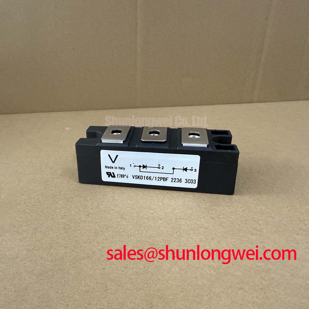
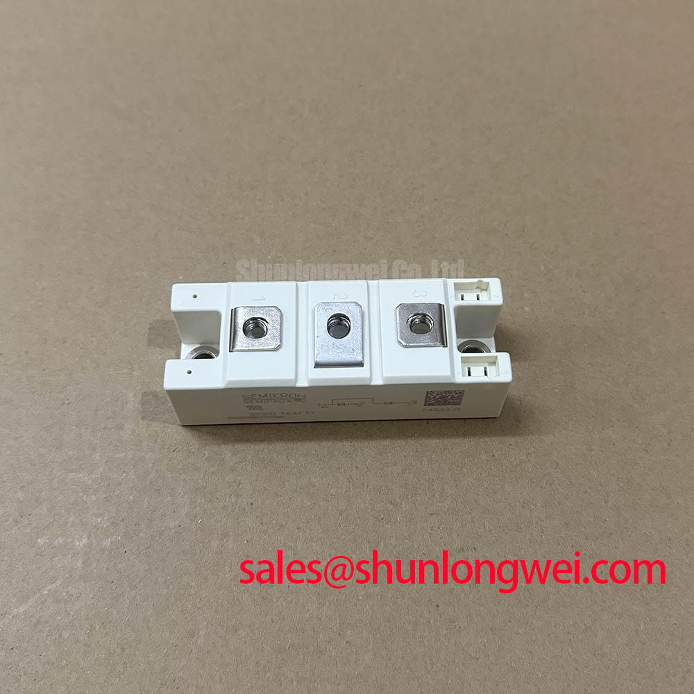
Probe the main terminals and gate or control connections with power isolated, then compare cold-state impedance and wiring continuity with a known-good assembly before changing the snubber network. The PRHMB150B12A is identified by the supplied official specification as a 1200 V, 150 A Nihon Inter (NIEC) thyristor / diode module in an isolated power package.
An RC snubber is a system-level design consideration rather than a fixed module parameter. Its purpose is to control transient voltage at the semiconductor terminals and reduce the possibility of unwanted dv/dt triggering. The resistor and capacitor values should be selected from the measured commutation waveform, source impedance, wiring inductance, and permitted leakage current. A saturable reactor may also be evaluated where the power stage shows excessive di/dt during current transfer.
Do not assign a fuse I2t coordination value or a snubber value to this part without the applicable NIEC electrical tables and the actual circuit waveform. The supplied factory data confirms voltage, current, package, and topology, but does not provide those additional figures. During testing, place the probe directly across the relevant power terminals and check the peak voltage, ringing frequency, and gate control response under the intended load.
Terminal orientation and busbar symmetry are equally important. Unequal conductor lengths can make one path switch or conduct differently from another, creating localized heating that may be incorrectly attributed to the module. For comparative sourcing, engineers may review PWB60A40 as a separate device option, but electrical and mechanical interchangeability must be established from the original equipment documentation.
PRHMB150B12A Thermal-Electrical Optimization: Coordination of Spark Gaps and MOVs
Capture the AC input surge path at the module terminals and inspect the MOV protection branch for clamping behavior, visible damage, and connection integrity before evaluating the thyristor junction response. IEEE 61000-4-5 testing concerns the complete equipment protection network; it does not constitute an independent compliance claim for the PRHMB150B12A.
A primary spark gap, MOV, and RC network can be coordinated as layered protection, with each device assigned a defined energy and voltage duty by the system designer. The MOV selection should consider the equipment supply waveform, repetitive operating voltage, surge energy, fault-current path, and protective disconnection method. The module’s official 1200 V voltage rating is an electrical boundary, not a substitute for transient testing.
Thermal inspection should compare terminal temperatures, heatsink contact, and current distribution between operating conditions. When several semiconductor paths are paralleled, designers should assess both static and dynamic current sharing rather than assume equal conduction. Positive temperature behavior cannot be treated as a universal guarantee for a particular internal structure unless it is stated in the applicable manufacturer documentation.
The isolated power-module construction supports insulated mechanical integration, but insulation coordination remains a system responsibility. For a front-end or auxiliary rectification stage, the independently specified PGH200N16 may be reviewed as a related component, not as an automatic replacement or guaranteed companion device.
Benchtop Waveform Tuning: Mitigating Stress During Half-Cycle Surge Testing
Record the voltage and current waveform through the complete sinusoidal half-cycle, then verify that the module has fully recovered before reverse voltage is reapplied. The supplied official data does not state an ITSM surge-current value, pulse duration, junction-temperature limit, or recovery interval for this model, so those values must not be inferred from the 150 A current rating.
For a medium-frequency induction melting and hardening furnace, the test bench should reproduce the actual transformer leakage, load behavior, firing sequence, and cooling condition. A current probe and differential voltage probe can reveal whether the observed stress originates from load commutation, control timing, wiring imbalance, or protection-device interaction. Compare successive pulses for thermal drift instead of judging safety from a single waveform.
Fuse selection and surge coordination require the manufacturer’s applicable pulse-rating and I2t data together with the fuse manufacturer’s clearing characteristics. If those tables are unavailable, use measured current and documented system fault analysis rather than publishing a presumed withstand value. This approach also prevents a normal-looking short-duration waveform from being mistaken for proof of repetitive surge capability.
Design tip: keep the high-current busbar paths physically symmetrical and validate the resulting peak voltage and current sharing with a properly rated oscilloscope setup during double-pulse or production-representative testing.
PRHMB150B12A Circuit Protection and Reliability: Evaluating Switching Loss
Measure reverse-current commutation directly at the diode path and correlate the waveform with device temperature, switching frequency, and EMI observations. The supplied factory specification classifies PRHMB150B12A as a 1200 V, 150 A thyristor / diode module, but it does not publish IRRM, trr, softness factor, or switching-loss curves.
Reverse-recovery performance is influenced by forward current, junction temperature, circuit stray inductance, applied reverse voltage, and gate-control conditions in the surrounding power stage. A sharp recovery current can increase voltage overshoot and common-mode radiation, while a softer waveform may alter dissipation elsewhere in the commutation loop. Engineers should therefore compare the measured recovery waveform with the original equipment’s approved operating envelope.
Minimize the parasitic commutation loop to reduce overshoot, keep sensing connections separate from high-current return paths, and verify peak voltage against the DC-link and insulation design during switching tests. External technical references such as the Mitsubishi Electric diode module lineup and Shindengen power semiconductor resources can help establish industry measurement terminology, but they do not supply missing PRHMB150B12A ratings.
For maintenance teams assessing furnace power assemblies, the related industrial TFT LCD technology guide may assist with the separate HMI and monitoring interface portion of the equipment. It should not be used to infer electrical or thermal limits for this power module.