Shunlongwei Co. ltd.
IGBT Module / LCD Display Distributor
Customer Service
+86-755-8273 2562
IGBT Module / LCD Display Distributor
“The device collects geographic information through GPS and attitude information from Electronic compass. According to the geographic information collected by GPS, combined with the position of communication satellites, it calculates the standard azimuth, pitch, and polarization parameters required for the satellite, and at the same time calculates the local and current magnetic bias. Angle data; by collecting electronic compass data, preliminary azimuth, pitch, and polarization data are obtained, of which pitch and polarization are the actual pointing values of the antenna, but the azimuth value is based on magnetic north as the standard measurement value;
“
1 System overview
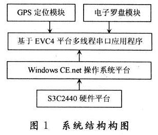
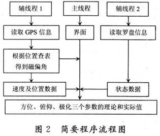
The device collects geographic information through GPS and attitude information from electronic compass. According to the geographic information collected by GPS, combined with the position of communication satellites, it calculates the standard azimuth, pitch, and polarization parameters required for the satellite, and at the same time calculates the local and current magnetic bias. Angle data; by collecting electronic compass data, preliminary azimuth, pitch, and polarization data are obtained, of which pitch and polarization are the actual pointing values of the antenna, but the azimuth value is based on the magnetic north as the standard measurement value; the magnetic declination data obtained by GPS , revise the azimuth value with magnetic north as the standard obtained from the electronic compass, and obtain more accurate true azimuth data with true north as the standard. The system structure is shown in Figure 1, and the multi-threaded application process structure based on the EVC4 platform is shown in Figure 2.
2 Hardware Design
In the design of this device, S3C2440 is selected as the main controller to form the hardware platform, and its rich external interfaces and high-speed processing capabilities are used to achieve real-time data acquisition, timely data processing, fast data transmission, and no additional interface equipment. Since the device needs to measure many parameters, the GPS and electronic compass use the RS 232 interface to ensure the accuracy of the measurement data and the consistency of the interface. The power supply is unified with +5 V lithium battery power supply.
3 Software Design
The device adopts ARM9 as the main controller, and uses Windows CE. net operating system as the system platform, using the EVC4 development environment as the development tool, the software adopts multi-thread structure, MFC and API programming technology, real-time acquisition of sensor data, calculation and correction of azimuth values, to achieve the purpose of accurate star alignment.
3.1 Overall program design
The device program adopts a multi-threaded structure. On the basis of the main thread (user interface thread), two auxiliary threads (worker threads) are added. The auxiliary thread is responsible for processing data collection, and the main thread is responsible for interface response, data fusion, and data Display. Thread processing adopts API instead of MFC programming, which increases the versatility of the program. The program also uses Suspend-Thread to suspend the thread, ResumeThread to resume the thread, and Exit-Thread to exit the thread.
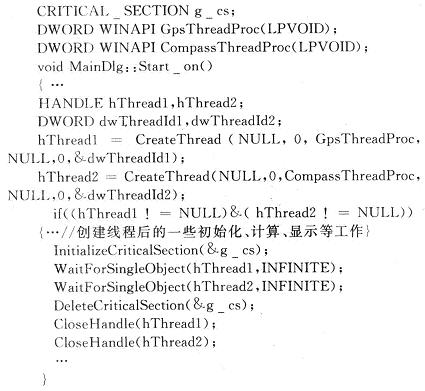
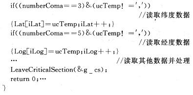
Thread synchronization adopts critical area (also known as critical area, namely CRITI-CAL SECTION) measures. First, use CRITICAL_SEC-TION to declare a global variable, then call InitializeCriticalSection to initialize, use EnterCriticalSection to enter the critical area, use LeaveCriticalSection to leave the critical area, and use Delete The -CriticalSection function removes critical sections. The key part of the code is as follows:

3.2 HMR3000 program design
The electronic compass data output format complies with the NMEA0183 communication protocol specification. The $PTNTHPR sentence is selected according to the requirements, and it is updated 30 times per second, which basically meets the requirements of real-time measurement. The data format of the $PTNTHPR statement is:
$PTNTHPR,,,,,,*hh
The meaning of each field is: azimuth value, azimuth status, pitch value, pitch status, roll value, roll status, hh checksum. The data collection program extracts the corresponding parameter value from the output statement on the basis of judging the normal state of each parameter. The part of the thread function code is as follows:
3.3 GPS module programming
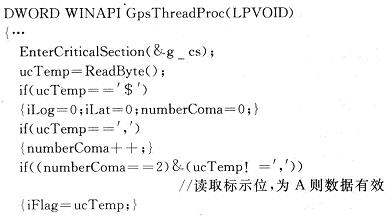
The data output format of the GPS module also complies with the NMEA0183 communication protocol specification. The $GPRMC sentence is selected according to the requirements, and the default update rate is used. The data format of the $GPRMC statement is:
$GPRMC,,,,,,,,,,,,,*hh.
The meanings of each field are: azimuth value, azimuth status, pitch value, pitch status, roll value, and roll status. The data collection program extracts the corresponding parameter value from the output statement on the basis of judging the normal state of each parameter. The part of the thread function code is as follows:
3.4 Calculation of the theoretical value of the star parameters
An important step in satellite communication is the accurate alignment of the satellite communication antenna with the communication satellite. Three parameters are required for star alignment: azimuth, pitch, and polarization. The following are the calculation formulas of the three parameters, where ψc is the longitude of the center of the satellite beam, ψs is the longitude of the satellite, ψg is the longitude of the receiving place, and θ is the latitude of the receiving place.
Satellite communication antenna azimuth calculation formula:

The polarization angle is usually located between the calculated values of Equation (3) and Equation (4). To simplify the calculation, Equation (3) is often used as the polarization angle calculation formula. The longitude and latitude of the receiving place are obtained through GPS acquisition. Combined with the longitude of the satellite, the mathematical function provided by the C language can easily calculate the three parameters required by the antenna to accurately align with the satellite: azimuth, pitch, and polarization. Provide theoretical standard value for star operation, simplify the star operation to compare the theoretical standard value, adjust the antenna so that the actual value is completely consistent with the theoretical value, so as to complete the star task.
3.5 Azimuth correction program design
What the electronic compass measures is the actual pointing value of the antenna. Since the electronic compass measures the azimuth value according to the geomagnetic field, the azimuth value is actually the azimuth value with the magnetic north as the standard, and the theoretical value is the azimuth value with the true north as the standard. There is a difference between the measured value of the electronic compass and the theoretical calculation value, which is the magnetic declination angle. To make the azimuth value measured by the electronic compass represent the azimuth value with true north as the standard, the magnetic declination must be corrected on the basis of the data measured by the electronic compass.
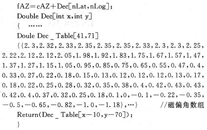
According to the IGRF2005 geomagnetic field model, using the magnetic declination calculation program provided by NOAA’s NG-DC, the magnetic declination data covering my country’s territory and surrounding areas are calculated one by one. °, form a 41 × 71 two-dimensional array, extract the magnetic declination data according to the longitude and latitude data, and perform operations with the collected compass data to correct the compass azimuth value, thereby obtaining a relatively accurate azimuth value representing the pointing of the object. Part of its code is as follows:
The azimuth data obtained from the electronic compass is corrected by the magnetic declination to form the true azimuth data with true north as the standard, so as to have the basis for comparing with the theoretical star parameters.
4 Applications and Results
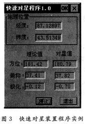
The device cleverly utilizes the GPS module and the electronic compass module. On the basis of collecting module data separately, the device uses geographic information to perform table lookup operations to obtain the local magnetic declination angle, and uses the magnetic declination angle to correct the azimuth to obtain more accurate azimuth and pointing data. This device adopts S3C2440ARM9 chip as main CPU, Windows CE. Net is the operating system platform; Honeywell HMR3000 is used for electronic compass, GARMINGPS25LVS for GPS, mushroom head antenna, single +5 V power supply, and RS 232 output interface. The system has high precision, good real-time performance and intuitive interface, and has wide application prospects. A certain type of satellite communication equipment, the antenna diameter is 1 m, works in the Ku band, the approximate calculation formula of the half-power lobe width is: θ=70λ/D, and the half-power lobe width θ=1.75° is obtained; through the magnetic declination angle The corrected electronic compass angle indication error is ψ=±0.5°, θ≥ψ, which meets the application requirements. In 2009, the magnetic declination angle of Urumqi was -2.93°. If the magnetic declination correction was not added, the total error was 2.93°+0.5°=3.43°, which exceeded the half-power beam width and could not complete the alignment. star mission. After the program runs, the interface is shown in Figure 3.
5 Conclusion
It has been proved that the device can be used to measure the position and attitude of objects that require ±0.5° for azimuth accuracy and ±0.1° for inclination and roll longitude after magnetic declination correction. After actual use and measurement in Kunming, Kashgar, Beijing and other places, the effect is good. The average time for star alignment has been reduced from the original uncertainty to less than 2 minutes (the average time of actual measurement is 1.4 minutes), and the improvement effect is obvious. Precautions in use: Since the electronic compass used by this device uses the principle of calculating the orientation based on the magnetoresistive sensing information of the earth’s magnetic field, this device should be kept away from framed buildings, iron ore plants, iron fences, iron Large-scale hard iron materials such as doors, iron windows, etc., avoid the occurrence of large measurement errors due to the influence of hard iron materials on magnetic lines of force.
The Links: AT080TN03 CM400HA-24A