


Content last revised on September 29, 2026
CM400HA-24A Circuit Protection & Reliability: Calibrating DC-Bus Operating Voltage Headroom Derating
| Model | CM400HA-24A |
|---|---|
| Manufacturer | Mitsubishi Electric |
| Product category | IGBT Module |
| Rated voltage | 1200 V — Official Specification |
| Rated current | 400 A — Official Specification |
| Package | Module — Official Specification |
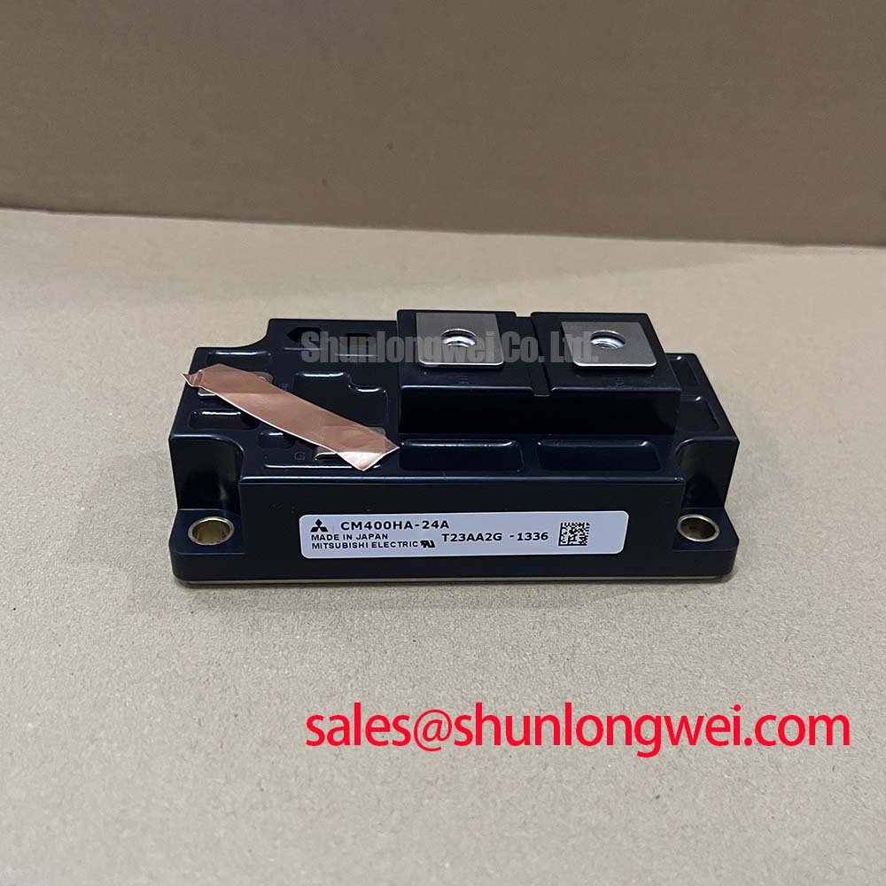
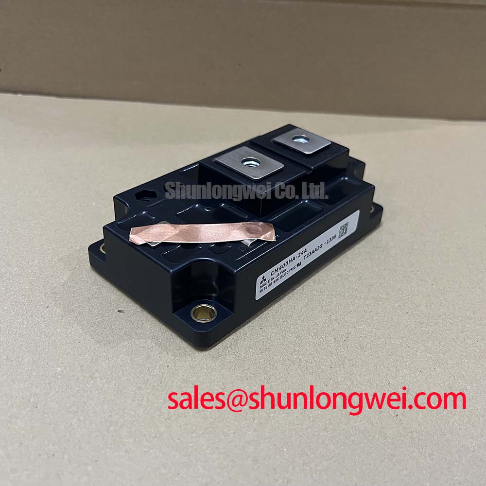
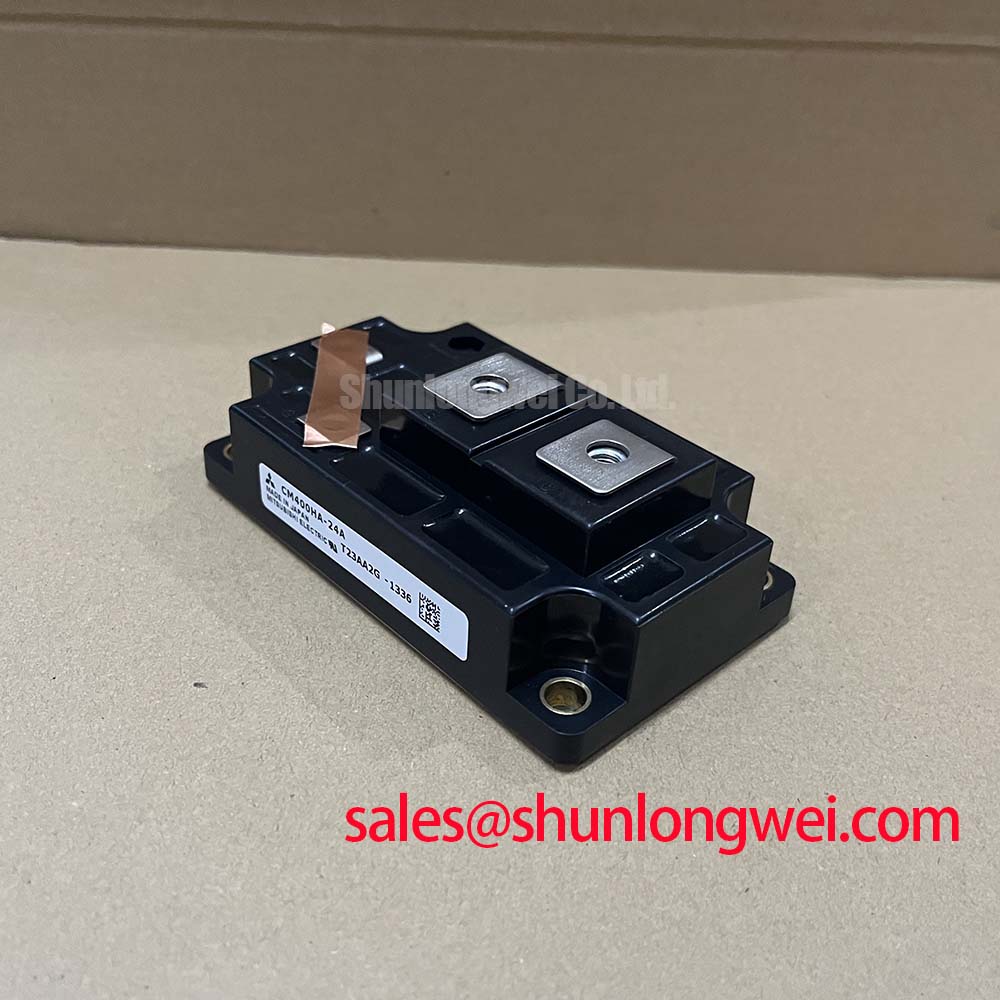
Measure the discharged DC link, identify collector and emitter connections from the terminal drawing, and trace the voltage imposed across each switch position. The CM400HA-24A has an official voltage rating of 1200 V; that figure is neither an approved continuous bus setting nor an insulation test voltage. Its 400 A current rating likewise does not establish permissible current under every cooling condition or switching duty.
Design Consideration: When evaluating this module for a utility-scale 1500 V central solar photovoltaic inverter, inspect the actual converter topology rather than equating the installation voltage with individual semiconductor stress. A switch position exposed directly to the full bus exceeds this module’s voltage rating. A multilevel arrangement requires verification of voltage sharing, switching overshoot, startup behavior, and abnormal operating states before compatibility can be established.
With the power circuit isolated and the gate held at emitter potential, compare collector-to-emitter diode-mode readings in both polarities against the circuit diagram and a known-good reference. Disconnect parallel paths when necessary: snubbers, discharge networks, and neighboring switches can influence the reading. A handheld meter cannot establish rated-voltage blocking capability or insulation withstand.
Design Consideration: Altitude-related cosmic-ray susceptibility and single-event burnout cannot be quantified from the voltage rating alone. A defensible FIT calculation needs device-specific susceptibility data and a defined exposure environment; no numerical rate or altitude derating percentage is established here. Consult Mitsubishi Electric Power Semiconductors & High-Power Modules for manufacturer technical resources relevant to device qualification.
For insulation checks, distinguish semiconductor blocking voltage from terminal-to-baseplate dielectric withstand. The explanation of dielectric strength and high-voltage breakdown testing provides background, not a CM400HA-24A acceptance procedure. Select test connections, voltage, duration, and acceptance limits from the applicable module specification and equipment test procedure; inspect contamination and conductor spacing separately.
Field Diagnostics & Commissioning: Baseplate Thermal Grease Layer Control in CM400HA-24A Topologies
Inspect the removed module’s thermal-interface imprint and heatsink contact surface for dry regions, trapped debris, and uneven seating. Record where contact is missing before cleaning the surfaces, because the pattern can help distinguish application inconsistency from mechanical distortion. Treat this as a bolted-module integration assessment, not a press-pack spring-pressure calibration or an assumed double-sided cooling arrangement.
Design Consideration: Apply the selected thermal-interface material according to its qualified assembly process. Excess material can increase thermal resistance, while incomplete coverage can leave poorly coupled regions. Set application thickness, mounting sequence, and fastener torque from the relevant mechanical instructions rather than assigning an unsupported universal value. Correct surface-condition problems instead of using thermal grease to compensate for excessive baseplate or heatsink deformation.
Bench Tip: Use ESD-controlled handling and compare cold-state measurements with a known-good reference under matching meter polarity and temperature conditions.
For replacement evaluation, compare the CM400HU-24H against the original terminal map, mounting footprint, electrical characteristics, and gate-driver requirements. A related model designation does not establish a verified direct replacement. Procurement records should preserve the complete part number and the equipment’s acceptance criteria, especially where the original driver and cooling assembly remain unchanged.
Design Consideration: If the equipment uses bootstrap-powered high-side drivers, assess the charge consumed by gate switching, driver quiescent current, leakage, and the longest interval without recharge. The permissible supply droop and recharge opportunity determine capacitor sizing; a value cannot be selected from the module’s current rating. When reviewing associated circuitry, evaluate the CM35MXA-24S by its own topology and ratings rather than assigning it a front-end rectifier role from its model name.
Preventing Spurious Faults: Thermal Time Constants and Peak Junction Guidelines for CM400HA-24A
Capture load current, case temperature, gate-drive status, and protection timing during the operating interval that produces the fault. Compare these records with a stable operating interval before attributing a trip to junction overheating. A heatsink measurement alone cannot resolve a short junction-temperature excursion, and a protection event does not independently identify the failed component.
Design Consideration: Estimate conduction and switching losses using characteristics applicable to the actual current, temperature, gate drive, and switching conditions. Average power is useful for steady operation, but pulsed overload assessment also needs the module’s transient junction-to-case thermal impedance. Keep the measured case-temperature reference consistent with the manufacturer’s measurement definition.
Engineering Calculation: A peak junction-temperature estimate combines the measured case temperature with the temperature rise produced by the loss waveform and the applicable transient thermal response. A multi-RC model is useful only when its coefficients represent this device and the stated thermal boundary conditions. Without those coefficients or a verified transient thermal-impedance curve, neither a numerical peak temperature nor an overload duration is justified.
Design Consideration: Inspect cooling flow, heatsink cleanliness, contact integrity, and sensor placement when repeated faults track operating load. Compare gate-drive undervoltage and desaturation records as well, since protection can respond to electrical conditions that resemble thermal trouble. Change one test condition at a time to preserve a meaningful comparison.
The related article The 1200 V CoolSiC™ MOSFET Advantage in Three-Phase Power Conversion offers context for another switching technology. Its device behavior and thermal assumptions should not be transferred to this Mitsubishi IGBT module or treated as manufacturer qualification evidence.
Transient Dynamics & Electrical Design: Suppressing C_res Induced Gate Voltage Spikes on CM400HA-24A
Probe gate-to-emitter voltage at the module connections while capturing collector-to-emitter switching voltage with appropriately rated measurement equipment. Compare the off-state gate waveform with the complementary switch transition to distinguish a real gate excursion from probe pickup. Include the measurement connection in that assessment, because an extended probe return can distort the observed waveform.
Design Consideration: Collector-to-gate capacitive coupling can disturb the off-state gate during rapid voltage transitions. Reduce the gate-loop area and provide a controlled return path, then verify the resulting waveform under representative bus voltage, load, and temperature. Do not assume a dedicated Kelvin-emitter terminal; establish the available auxiliary connections from the terminal drawing.
Design Consideration: An active Miller clamp or negative off-state bias can be evaluated when supported by the driver architecture and the module’s gate-voltage limits. Clamp timing, sink capability, and bias magnitude remain system-determined. Assess driver isolation CMTI separately from the module’s voltage rating, and confirm that commanded dead time produces adequate separation at the actual power terminals.
Check DC-link connections and snubber placement when turn-off overshoot accompanies the gate disturbance. A MOV or other suppression element requires coordinated voltage, energy, and repetitive-duty assessment; it is not a substitute for controlling commutation-loop inductance. Record gate extrema, collector-voltage peaks, and protection response after each change so that the repair decision rests on measured electrical behavior.