

Content last revised on September 19, 2026
S5C-225HV Product Overview
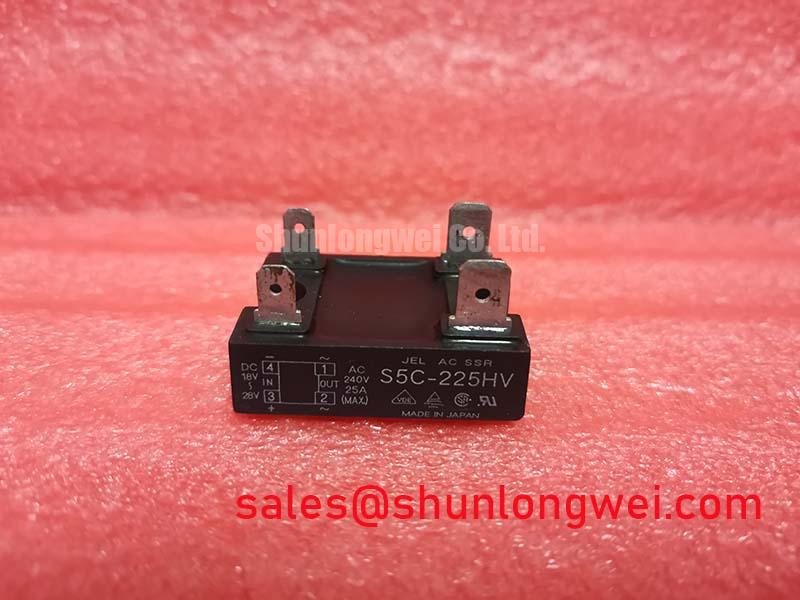
With power removed, inspect the S5C-225HV terminal area, housing condition, and mating conductors before reconnecting a traction inverter, then compare the installed unit’s current requirement with its 120.0A rated current value under the applicable datasheet conditions.
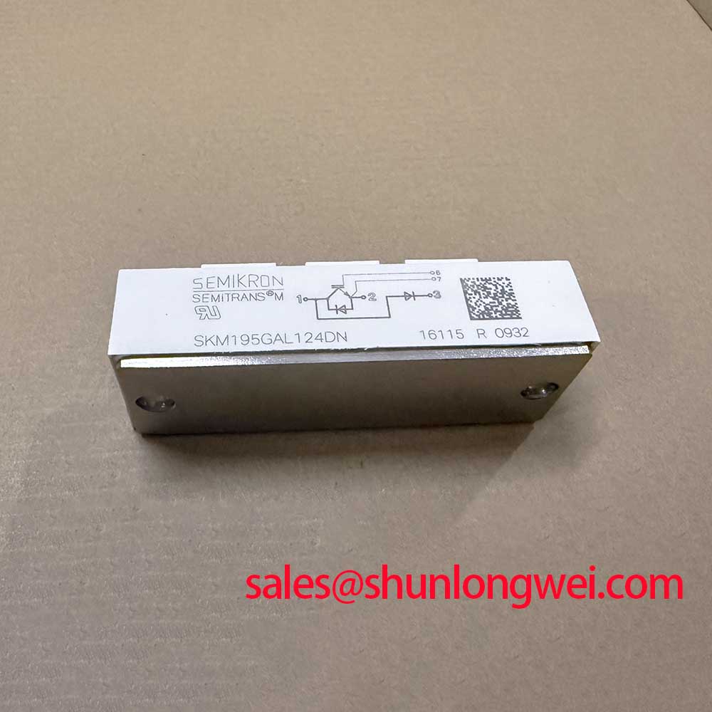
The S5C-225HV is a Sanken IGBT Module supplied in a SIP / ZIP Module package format. The available product listing identifies its working-voltage classification as Standard Industrial Rating. These are listed product specifications for this model; the original equipment documentation should be consulted for terminal assignment, driver supply requirements, switching limits, insulation ratings, and thermal limits before a repair or redesign is approved.
| Parameter | Specified Value | Specification Status |
|---|---|---|
| Manufacturer | Sanken | Official product identification |
| Model | S5C-225HV | Official product identification |
| Rated Current | 120.0A | Rated value subject to applicable datasheet conditions |
| Working Voltage | Standard Industrial Rating | Listed classification; verify in the original documentation |
| Package | SIP / ZIP Module | Listed product specification |
Transient Dynamics & Electrical Design: Isolation Boundary Review for S5C-225HV
Start an electrical review by separating the power loop, gate-drive loop, control ground, and any chassis-referenced signals on the inverter drawing. The available S5C-225HV product information does not state a reinforced-isolation voltage or common-mode transient immunity rating. Those properties must therefore be verified from the original equipment design records and driver documentation rather than assigned to the module.
In a motor drive, a rapid collector-emitter voltage transition can couple through stray capacitance into the gate path. A gate pulse observed during an intended off-state does not establish one single root cause. It can arise from common-mode coupling, gate-return routing, a weak gate pull-down path, connector resistance, or an unsuitable driver reference. Design Consideration: keep the gate-drive return physically associated with its corresponding switching path, minimize loop area, and inspect whether the driver reference shifts during switching with an isolated measurement method.
For equipment with control interfaces crossing between power and logic sections, the system integrator should assess creepage, clearance, connector routing, and contamination exposure against the applicable end-equipment standard. A solid-state switching stage can provide galvanic separation only where the full device architecture includes it; the general operating concepts of a solid-state relay are useful context, but they do not establish an isolation specification for this IGBT module.
During a repair evaluation, check the gate command against the emitter or designated driver return at the module connection, not only at the controller board. If unwanted movement appears near the Miller plateau, examine the off-state drive path, clamp behavior where present, and power-loop coupling. For a broader review of gate turn-off practices, consult Evolution of Negative Off-Bias Gate Drive Circuits; that reference should be applied as a system-level test topic, not as an assumed factory requirement for the S5C-225HV.
Benchtop Waveform Tuning: Output Filter and Reactor Choices for S5C-225HV
Before changing output hardware, capture phase voltage and current at the operating condition that reproduces the fault. Long motor cables behave as transmission paths, and an impedance mismatch between cable and motor can reflect switching energy back toward the inverter terminals. Under certain conditions, reflected peaks can approach twice the DC bus voltage. This is an Engineering Consideration for the cable and inverter system, not an official voltage-stress statement for the S5C-225HV.
A dv/dt reactor and a sinusoidal output filter solve different system problems. A reactor principally moderates the rate of current and voltage change seen by the cable and motor. A sinusoidal filter is evaluated where the motor requires a lower-ripple waveform at its terminals. Selection depends on motor-lead length, carrier strategy, motor insulation condition, allowable voltage drop, control-loop response, and measured waveforms. Designers should compare the pre-filter and post-filter traces before deciding which approach addresses the observed stress.
Design Consideration: contain commutation-loop inductance by using short, paired conductor paths between the DC-link capacitor and switching stage. Place any approved snubber film capacitor close to the switching loop so its high-frequency path does not become a long antenna. The resulting benefit must be verified with a properly compensated probe and peak-voltage measurements against the actual DC-link voltage during switching tests.
In forklift low-voltage traction drives, regenerative braking can return energy to the DC link. The braking chopper, braking resistor, battery-management behavior, and deceleration profile should be reviewed together when bus excursions occur. A power-stage module cannot independently define how much regenerative energy the complete vehicle system can absorb. Where a topology review includes a separate power stage, the SKM100GB063D can be documented as a related device for objective circuit comparison, subject to its own datasheet and mounting constraints.
💡 Pro Tip: Measure turn-off voltage at the module-side power loop before changing gate components, because a probe point at the remote DC-link bus can hide the overshoot that matters.
Preventing Spurious Faults: Altitude and SEB Review for S5C-225HV
No manufacturer-supplied FIT rate, cosmic-ray susceptibility figure, altitude derating curve, or single-event burnout limit is provided in the available S5C-225HV parameters. It would be inappropriate to calculate a failure-in-time value or prescribe a fixed DC-bus derating from the information available. High-altitude deployment should instead be treated as a Design Consideration requiring the vehicle or inverter manufacturer’s environmental qualification data and applicable safety assessment.
At elevated locations, lower air density can affect external insulation coordination and cooling-system behavior, while neutron-related semiconductor considerations require device-specific evidence. These mechanisms should not be merged into a single diagnosis when a traction inverter trips intermittently. Record altitude, enclosure temperature, heat-sink condition, DC-link trend, motor current, fault-code sequence, and switching waveform where measurement access permits. This establishes whether the event follows thermal loading, bus transients, control noise, or another system condition.
Spurious fault reports also warrant a check of dead-time behavior and shoot-through protection. Dead time is determined by the complete driver, switching device characteristics, power-loop layout, and operating condition. Engineering Recommendation: validate non-overlap at the actual module terminals during dynamic testing, then confirm that the resulting switching loss and waveform peaks remain within the limits established by the original system design.
When comparing an installed assembly with a related reference part, P950A may be reviewed as a same-family sourcing reference. Package outline, terminal function, gate-drive requirements, protection behavior, thermal interface, and official electrical ratings must still be confirmed individually before any substitution decision.
Assembly Integrity & Layout Architecture: Thermal Path Review for S5C-225HV
The supplied product data does not include junction-to-case thermal impedance, transient thermal impedance curves, maximum junction temperature, mounting torque, or baseplate-flatness requirements for the S5C-225HV. Peak junction-temperature margins therefore cannot be calculated responsibly from the listed information. Use the original module documentation and the host equipment’s thermal design records when a pulsed-overload event, blocked cooling path, or repeated braking cycle is under review.
Inspect the mounting surface for contamination, corrosion, raised burrs, and uneven contact before fitting the module. Apply thermal interface material according to the material supplier’s process guidance and the equipment manufacturer’s mechanical instructions. Uneven clamp force or an uncontrolled layer of interface material can increase thermal resistance, but it does not prove that the semiconductor itself is damaged. Compare heat-sink temperature rise, current loading, airflow condition, and module-side electrical behavior before replacing parts.
For assemblies using flat-pressure hardware, spring elements and fasteners should be tightened in the documented sequence so pressure develops evenly across the specified mounting area. Design Consideration: use a calibrated tool and avoid assuming a generic fastener torque is valid for this package. Mechanical stresses must remain separate from electrical terminal stresses; busbars should reach the module without forcing the housing or twisting terminal connections.
Thermal verification is most useful when it follows the actual duty cycle. Capture the current profile, switching pattern, braking interval, heat-sink response, and ambient condition, then compare those records with a known-good machine where possible. Intelligent power-module families such as Infineon CIPOS™ Maxi IPM Series illustrate that protection and drive integration vary substantially by product architecture; such features must not be presumed in the discrete SIP / ZIP implementation of the S5C-225HV.