

Content last revised on September 18, 2026
Preventing Spurious Faults: Reverse Recovery and Commutation Checks for SKB72/16
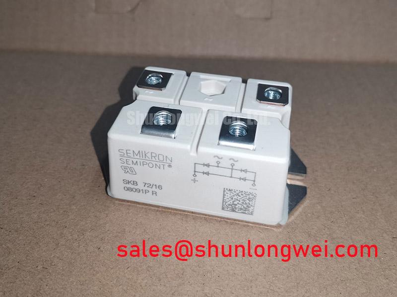
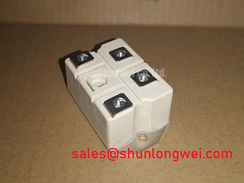
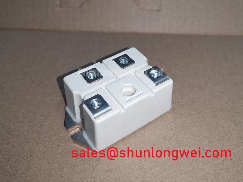
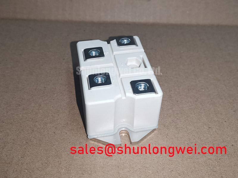
Start the bench check with the equipment isolated: inspect the Semipont housing, confirm the nameplate marking, and compare the rectifier position with the original wiring record before applying any test voltage. The Semikron SKB72/16 is specified as a bridge rectifier module with a voltage rating of 1600 V and a current rating of 72 A. These are the core product specifications available for this listing; the system designer must verify the complete electrical and mechanical limits from the applicable manufacturer documentation before replacement.
In a high-current DC rectifier, unexplained fuse operation or abnormal switching noise should be investigated at the complete commutation path rather than assigned to the rectifier module alone. The SKB72/16 is a bridge rectifier module, so the practical first task is to identify the bridge terminals from the equipment schematic and confirm that the replacement position matches the original polarity and phase arrangement. Do not infer terminal functions from the package outline alone when the original documentation is unavailable.
Reverse recovery current and recovery behavior belong to the complete diode, transformer, line impedance, wiring, and load system. The available product data supplied for this page confirms the 1600 V voltage rating, 72 A current rating, and Semipont housing, but it does not provide a verified reverse recovery charge, peak reverse recovery current, recovery time, or temperature coefficient. Those values should be obtained from the relevant technical document before calculating switching loss, EMI behavior, or commutation stress.
For a service check, compare the suspect bridge with a known-good signal path. Inspect phase conductors for loose lugs, heat discoloration, damaged insulation, and altered routing. A high-current loop with excessive stray inductance can produce overshoot during commutation, while poor transformer balance or control timing can create unequal current sharing. Designers should minimize parasitic loop inductance and verify peak voltage with an oscilloscope during controlled switching tests against the DC-link rating.
The Semikron-Danfoss Power Electronics and Modules Official Hub is a useful reference point for product family information. It should not be treated as a substitute for the exact SKB72/16 technical documentation or the equipment manufacturer’s circuit data.
SKB72/16 Circuit Protection and Reliability in High-Current DC Rectifier Topologies
A 6-pulse bridge uses three-phase input groups to produce a six-pulse rectified waveform. A 12-pulse arrangement normally combines two six-pulse bridges with a suitable phase-shifting transformer arrangement. Interphase transformer behavior, transformer leakage impedance, line impedance, firing or synchronization controls where applicable, and load distribution determine how current is shared across the complete rectifier system. The SKB72/16 should therefore be evaluated as one bridge module within the topology, not as an independent guarantee of kiloampere output capability.
For a high-current green hydrogen electrolyzer DC power rectifier, the system integrator should verify the required DC voltage, continuous load current, overload profile, cooling method, transformer secondary arrangement, and harmonic mitigation strategy. A 12-pulse configuration can reduce selected characteristic line harmonics compared with a single 6-pulse arrangement, but actual performance depends on phase displacement, source impedance, transformer balance, and the operating point. Harmonic measurements at the installation supply are required before claiming compliance with any site power-quality requirement.
The stated 72 A rating is a product specification for the listed module. It must not be multiplied directly by the number of bridges without checking the manufacturer’s conditions for current, temperature, cooling, duty cycle, and parallel operation. If the assembly uses parallel current paths, designers should verify equal conductor impedance and thermal balance through measured current sharing. The voltage selection must also account for the maximum applied repetitive voltage and transient conditions in the actual rectifier cabinet.
For a neutral cross-reference during procurement, engineers may review the related SKD 25/14 product page. It is a separate device and should not be treated as a drop-in replacement unless the original equipment documentation confirms electrical ratings, terminal geometry, cooling requirements, and mounting compatibility.
SKB72/16 Operational Boundaries: Short-Circuit Withstand and Fuse Coordination
A semiconductor fuse must be coordinated with the bridge, bus structure, transformer, and prospective fault current. The key comparison is the fuse clearing energy against the semiconductor’s permitted surge and short-circuit withstand data. No fuse I²t coordination value, surge current rating, or short-circuit withstand limit has been provided in the product information available for this page, so a specific fuse part number or clearing threshold cannot be stated responsibly.
During a dead short, the installed fuse and the upstream source determine how rapidly current rises and how much energy reaches the rectifier before interruption. The service engineer should record the fuse manufacturer, fuse class, rated voltage, prospective fault current, pre-arcing I²t, total clearing I²t, and interrupt rating. These values must then be checked against the exact SKB72/16 documentation and the equipment protection study. A 1600 V module rating does not, by itself, define the safe fuse coordination point for every transformer and DC bus.
Inspect the complete protection path after any high-energy event. Check the fuse clips, busbar joints, transformer terminals, enclosure barriers, and rectifier mounting area for evidence of thermal or mechanical movement. Measure the isolated bridge according to the equipment service procedure, using a controlled test method and comparing readings with a known-good unit. A single resistance result should not be used as the sole failure diagnosis because connected capacitors, snubbers, transformers, and parallel semiconductor paths can influence the measurement.
Where the rectifier is part of a high-current electrolyzer supply, protection coordination should also consider controlled precharge, DC-bus discharge, contactor sequencing, and the fault response of the converter downstream. These are system functions. The module’s published ratings must be checked alongside the cabinet protection design rather than used as a substitute for it.
Benchtop Waveform Tuning: Mechanical Mounting and Thermal Contact
Before waveform testing, remove contamination from the heatsink interface and inspect the mounting surface for burrs, distortion, and uneven contact marks. The SKB72/16 uses a Semipont package, while the supplied product data does not state a verified mounting torque, baseplate dimension, thermal resistance, or thermal interface thickness. Use the exact manufacturer mechanical specification and the heatsink assembly drawing instead of transferring values from another Semikron package.
Uniform contact pressure is important because uneven mounting can create local thermal concentration and mechanical stress. Apply the approved thermal interface material in the manner specified by the equipment or module documentation, then tighten the fasteners in the prescribed sequence. After mounting, confirm that the module body remains seated without rocking and that the power terminals are not being forced into alignment by the busbars.
⚠️ Field Alert: De-energize and discharge the DC link before touching the bridge or its terminals, and use only the specified mounting hardware and torque procedure for the actual Semipont assembly.
For benchtop verification, monitor the DC bus, phase current, rectifier output ripple, and heatsink temperature during a controlled load increase. If waveform ringing appears, review busbar geometry, transformer leakage, snubber condition, probe grounding, and oscilloscope bandwidth before attributing the behavior to the SKB72/16. Keep the measurement loop short and use a suitable differential probe for floating high-voltage nodes.
The Ultimate IGBT Knowledge Base provides broader power semiconductor background for engineers reviewing switching stress and thermal paths. The SKB72/16 remains a bridge rectifier module, so its final application limits must come from its own documentation and the rectifier system test results.
When reviewing related module families, the Semikron MiniSKiiP® Power Modules page can help with general product family orientation. Package family information does not establish interchangeability; terminal layout, voltage rating, current rating, cooling, insulation, and mechanical fit must all be verified for the intended equipment.