


Content last revised on March 31, 2026
SKR141F17: 1700V Fast Recovery Diode, Stud Mount Design
Introduction to the SKR141F17 Fast Recovery Rectifier Diode
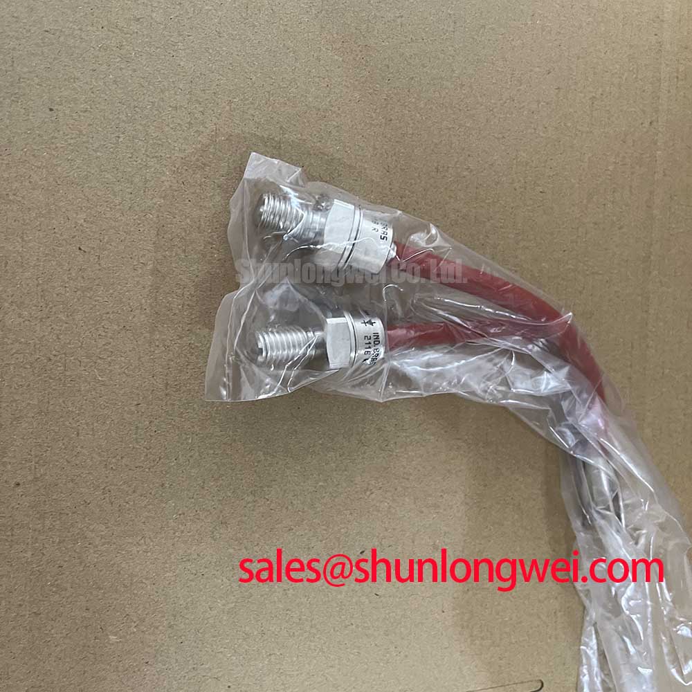
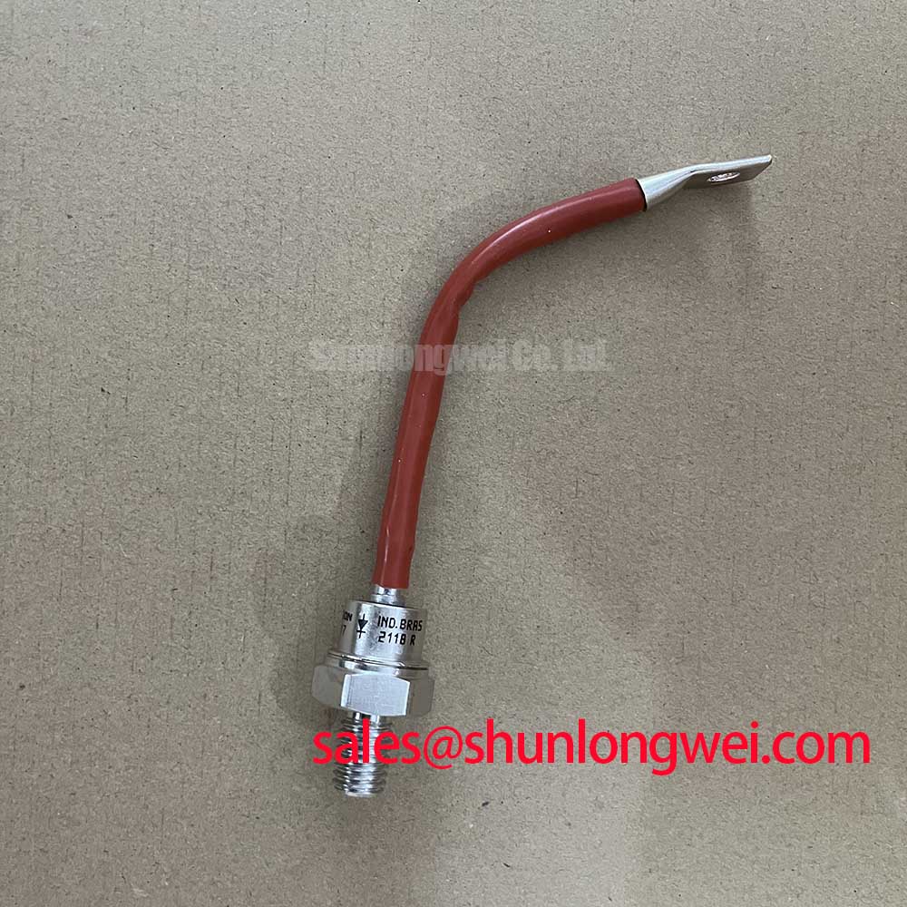
The SKR141F17 is a 1700V fast recovery rectifier diode featuring a robust, hermetically sealed stud housing for exceptional mechanical stability and environmental resilience. With key specifications of 1700V | 145A | Tj max 180°C, this component delivers two primary engineering benefits: superior long-term reliability in high-vibration settings and a simplified, direct thermal path for effective heat dissipation. Its stud-mount construction directly addresses the engineering need for a secure, durable rectifier that resists mechanical stress, ensuring consistent performance in demanding industrial power conversion systems.
Application Scenarios & Value
Engineered for Demanding Industrial Environments
The SKR141F17 is designed for high-power applications where both electrical performance and mechanical integrity are critical. Its architecture provides tangible value in systems that experience significant operational stress, whether thermal, electrical, or physical.
- Welding Power Supplies: In welding equipment, the diode's fast recovery characteristics (low t_rr) minimize switching losses, while its robust stud housing withstands the high-vibration and electrically noisy environment common on manufacturing floors.
- Industrial Battery Chargers: For large-scale battery charging systems, such as those for forklifts or backup power, the SKR141F17 provides a dependable rectification solution. The hermetically sealed case protects the semiconductor element from corrosive fumes or airborne contaminants often present in industrial settings.
- High-Power DC Supplies: This diode serves as a foundational component in the output stages of DC power supplies for applications like electrolysis, DC motor drives, and general industrial process control, where uptime and component longevity are paramount.
For high-frequency inverter designs where low saturation voltage is a primary concern, the CM600DX-24T IGBT module offers an alternative technological approach for the switching stage.
Best Fit Scenario: With a reverse recovery charge (Q_rr) of just 200 µC at 100 A/µs, the SKR141F17 is the optimal choice for high-voltage freewheeling or rectifier circuits requiring both speed and ruggedness.
Industry Insights & Strategic Advantage
A Foundation for Resilient Power Conversion Systems
In the push towards Industry 4.0 and increased automation, electronic components are being deployed in progressively harsher environments. The design philosophy of the Semikron SKR141F17 directly supports this trend. Its focus on mechanical and environmental robustness translates to a lower total cost of ownership (TCO) by reducing maintenance cycles and minimizing downtime caused by component failure. The hermetically sealed metal case is a critical feature for achieving long operational life in applications exposed to humidity, dust, or chemical vapors, ensuring system reliability aligns with the strategic goals of modern, continuous-operation facilities. For a broader understanding of how power modules form the core of modern systems, explore our guide on the backbone of high-efficiency power systems.
Intra-Series Comparison & Positioning
Positioning the SKR141F17: Robustness Meets Performance
Within the broader landscape of power rectifiers, the SKR141F17 distinguishes itself through its single-component, stud-mount form factor. While multi-device IGBT modules integrate multiple diodes and transistors for compact system design, the discrete nature of a stud-mount diode offers distinct advantages in specific scenarios.
What is the primary benefit of its stud-mount design? Enhanced thermal and mechanical reliability by creating a direct, high-pressure connection to the heatsink. This approach provides unparalleled flexibility in mechanical layout and thermal design, allowing engineers to optimize the cooling for a single, critical component. This contrasts with integrated modules, where the thermal management strategy must accommodate all internal components simultaneously. The SKR141F17 is therefore positioned not as a replacement for integrated modules, but as a specialized solution for applications where a single, high-reliability rectifier is needed and where mechanical robustness is a chief design consideration.
Technical Deep Dive
Dissecting the Robust Design and Fast Recovery Characteristics
The engineering value of the SKR141F17 is rooted in its fundamental construction and electrical properties. The "SKR" designation denotes a stud cathode configuration with a standard M16x1.5 thread, which simplifies system assembly. This design allows the device to be torqued to a precise specification (typically 15 ± 2 Nm), establishing a low-resistance thermal and electrical path directly from the component case to the heatsink. This direct metal-to-metal contact is a key factor in its long-term reliability under conditions of thermal cycling and vibration, mitigating risks associated with solder fatigue in other package types.
Electrically, its "fast recovery" nature is defined by a low reverse recovery time (t_rr) and charge (Q_rr). When the diode switches from a conducting to a blocking state, a brief reverse current flows. A lower Q_rr means less energy is dissipated during this transition, which is crucial for reducing switching losses, especially in circuits operating at higher frequencies. This efficiency directly impacts the thermal load on the diode and the overall system.
Key Parameter Overview
Core Specifications for System Integration
The following parameters are critical for the successful integration of the SKR141F17 into any power system. The values presented here are based on the official manufacturer's datasheet for accurate design and simulation.
Interpreting key specifications is essential for robust design. The Repetitive Peak Reverse Voltage (VRRM) of 1700V provides a significant safety margin for operation on high-voltage DC buses, protecting the device from transient overvoltages. The Average Forward Current (IFAVM) of 145A is analogous to the continuous flow rating of a pipeline; it represents the maximum continuous current the device can handle under specified case temperature conditions (Tc = 122°C). Finally, the Thermal Resistance, Case to Heatsink (Rth(c-s)), at 0.05 K/W, is a measure of how effectively heat can be transferred from the device case to the cooling apparatus, a critical factor in any thermal management strategy. For more insights on interpreting these documents, refer to our guide on decoding IGBT datasheets.
| Electrical Characteristics | |
|---|---|
| Repetitive Peak Reverse Voltage (VRRM) | 1700 V |
| Average Forward Current (IFAVM) at Tc=122°C | 145 A |
| RMS Forward Current (IFRMS) at Tc=100°C | 270 A |
| Surge Forward Current (IFSM), 10 ms, 25°C | 2500 A |
| Threshold Voltage (VT(TO)) | 1 V |
| Slope Resistance (rT) | 1.85 mΩ |
| Reverse Recovery Charge (Qrr) at di/dt = -100 A/µs | 200 µC |
| Thermal and Mechanical Characteristics | |
| Max. Junction Temperature (Tj max) | 180 °C |
| Operating Temperature Range (Tj op) | -40 to 180 °C |
| Thermal Resistance, Junction to Case (Rth(j-c)) | 0.2 K/W |
| Thermal Resistance, Case to Heatsink (Rth(c-s)) | 0.05 K/W |
| Mounting Torque | 15 ± 2 Nm |
| Case Style | G 23 (Stud Cathode) |
Frequently Asked Questions
What is the significance of the specified mounting torque for the SKR141F17?
Applying the correct mounting torque (15 ± 2 Nm) is critical for ensuring both optimal thermal performance and long-term mechanical reliability. Under-torquing can lead to a high thermal resistance at the case-to-heatsink interface, causing the device to overheat. Over-torquing can damage the device's stud or internal structure. Adhering to the specified range guarantees a secure connection that withstands vibration and provides a consistent, low-resistance path for heat dissipation.
How does the hermetically sealed case benefit my application?
The hermetically sealed metal case provides a robust barrier against environmental contaminants such as moisture, dust, and corrosive gases. This makes the SKR141F17 an excellent choice for systems deployed in challenging industrial, marine, or outdoor environments where non-sealed plastic components might degrade over time, leading to premature failure.
For your system's design and evaluation needs, please refer to the official datasheet. Contact us for inquiries regarding this component and to discuss how it can be integrated into your power conversion architecture.