Shunlongwei Co. ltd.
IGBT Module / LCD Display Distributor
Customer Service
+86-755-8273 2562
IGBT Module / LCD Display Distributor
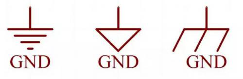
GND (Ground) on the circuit diagram and on the circuit board represents the ground line or 0 line. GND means the common terminal, which can also be said to be the ground, but this ground is not the real ground. It is a ground assumed for the application, and for the power supply, it is the negative pole of a power supply. It is different from the earth. Sometimes it is necessary to connect it to earth, and sometimes it is not, depending on the situation.
The signal grounding of the device may be a point or a piece of metal in the device as the ground reference point of the signal, which provides a common reference potential for all signals in the device.
There are single-point grounding, multi-point grounding, floating ground and mixed grounding.
Single-point grounding means that only one physical point in the entire circuit system is defined as the grounding reference point, and all other points that need to be grounded are directly connected to this point. In low frequency Circuits, there is not much influence between wiring and components. Usually a circuit with a frequency less than 1MHz is grounded at one point.
Multi-point grounding means that each grounding point in an Electronic device is directly connected to the ground plane closest to it (ie, the metal backplane of the device). In high frequency circuits, the influence of parasitic capacitance and inductance is greater. Usually circuits with frequencies greater than 10MHz are often grounded at multiple points.
Floating, that is, there is no conductor connection between the ground of the circuit and the earth. Virtual ground: A point that is not grounded but has the same potential as ground.
The advantage is that the circuit is not affected by the electrical properties of the earth. The floating ground can make the isolation resistance between the power ground (strong electric ground) and the signal ground (weak electric ground) very large, so it can prevent the electromagnetic interference caused by the circuit coupling of the common ground impedance.
The disadvantage is that the circuit is susceptible to parasitic capacitance, which makes the ground potential of the circuit fluctuate and increases the inductive interference to the analog circuit.
“Earth” is a very important concept in electronic technology. Since there are many types and functions of “earth”, it is easy to be confused, so let’s summarize the concept of “earth”.
“Grounding” includes the internal signal grounding of the device and the grounding of the device. The concepts and purposes of the two are different. The classic definition of “earth” is “an equipotential point or plane that serves as a reference for a circuit or system”.
One: The signal “ground”, also known as the reference “ground”, is the reference point of zero potential, and is also the common end of the circuit signal loop.
(1) DC ground: DC circuit “ground”, zero potential reference point.
(2) AC ground: the neutral line of AC power. should be distinguished from the ground wire.
(3) Power ground: the zero-potential reference point for high-current network devices and power amplifier devices.
(4) Analog ground: the zero-potential reference point for amplifiers, sample-and-holds, A/D converters and comparators.
(5) Digital ground: Also called logic ground, it is the zero-potential reference point of digital circuits.
(6) “Hot ground”: The switching power supply does not need a power frequency transformer, and the “ground” of its switching circuit is related to the mains grid, the so-called “hot ground”, which is charged.
(7) “Cold ground”: Because the high-frequency transformer of the switching power supply isolates the input and output ends; and because the feedback circuit of the power supply often uses a photocoupler, it can not only transmit the feedback signal, but also isolate the “ground” of both sides; The ground is called “cold ground” and it is not charged.
signal ground
The signal grounding of the device may be a point or a piece of metal in the device as the ground reference point of the signal, which provides a common reference potential for all signals in the device.
There are single-point grounding, multi-point grounding, floating ground and mixed grounding. (The floating ground is mainly introduced here) Single-point grounding means that only one physical point in the entire circuit system is defined as the grounding reference point, and all other points that need to be grounded are directly connected to this point. In low frequency circuits, there is not much influence between wiring and components. Usually a circuit with a frequency less than 1MHz is grounded at one point. Multi-point grounding means that each grounding point in an electronic device is directly connected to the ground plane closest to it (ie, the metal backplane of the device). In high frequency circuits, the influence of parasitic capacitance and inductance is greater.Usually circuits with frequencies greater than 10MHz are often used
Ground at multiple points. Floating, that is, there is no conductor connection between the ground of the circuit and the earth. 『Virtual ground: A point that is not grounded, but has the same potential as ground. 』The advantage is that the circuit is not affected by the electrical properties of the earth. The floating ground can make the isolation resistance between the power ground (strong electric ground) and the signal ground (weak electric ground) very large, so it can prevent the electromagnetic interference caused by the circuit coupling of the common ground impedance. The disadvantage is that the circuit is susceptible to parasitic capacitance, which makes the ground potential of the circuit fluctuate and increases the inductive interference to the analog circuit. A compromise solution is to connect a large bleeder resistor between floating ground and common ground to discharge the accumulated charge. Be careful to control the resistance of the release resistor, too low resistance will affect the qualification of the leakage current of the device.
1: Application of floating technology
aThe AC power ground is separated from the DC power ground
Generally, the neutral wire of the AC power supply is grounded. However, due to the existence of grounding resistance and the current flowing on it, the potential of the zero line of the power supply is not the zero potential of the earth. In addition, there is often a lot of interference on the neutral line of the AC power supply. If the AC power supply ground is not separated from the DC power supply ground, it will affect the normal operation of the DC power supply and subsequent DC circuits. Therefore, using the floating technology that separates the AC power ground from the DC power ground can isolate the interference from the AC power ground wire.
b Floating technology for amplifiers
For amplifiers, especially those with small input signals and high gain, any small interference signal at the input may cause abnormal operation. Therefore, using the floating technology of the amplifier can block the entry of interference signals and improve the electromagnetic compatibility of the amplifier.
c Precautions for floating technology
1) Try to improve the ground insulation resistance of the floating system, which is beneficial to reduce the common mode interference current entering the floating system.
2) Pay attention to the parasitic capacitance of the floating system to the ground. High-frequency interference signals may still be coupled into the floating system through the parasitic capacitance.
3) Floating ground technology must be combined with electromagnetic compatibility technologies such as shielding and isolation in order to receive better expected results.
4) When using floating technology, attention should be paid to the hazards of static electricity and voltage counterattack to equipment and people.
2: Hybrid grounding
Hybrid grounding causes the grounding system to exhibit different characteristics at low and high frequencies, which is necessary in broadband sensitive circuits. Capacitors have high impedance to low frequencies and DC, thus avoiding the formation of ground loops between the two Modules. When separating the DC ground and the RF ground, connect the DC ground of each subsystem to the RF ground through a 10-100nF capacitor. The two grounds should be connected with low impedance at one point, and the connection point should be selected at the highest flip speed ( di/dt) point where the signal exists.
Two: The equipment is connected to the ground
In engineering practice, in addition to seriously considering the signal grounding inside the equipment, the signal ground of the equipment, the chassis and the ground are usually connected together, and the ground is used as the grounding reference point of the equipment.The purpose of connecting the equipment to the ground is to
1) Protective ground, protective grounding is to make a good electrical connection between the non-charged metal casing (or frame) and the grounding device during normal operation of the equipment. A wiring method set up to protect personnel safety. One end of the protective “earth” wire is connected to the housing of the electrical appliance, and the other end is reliably connected to the earth.
2) Anti-static grounding to discharge the accumulated charges on the chassis, to avoid the accumulation of charges to increase the potential of the chassis, resulting in unstable circuit operation.
3) Shield the ground to prevent the equipment from changing the potential of the equipment to the ground under the action of the external electromagnetic environment, resulting in unstable operation of the equipment.
In addition, there are lightning protection grounding and audio dedicated ground in audio.