

Content last revised on October 18, 2026
Benchtop Waveform Tuning: Mitigating Stress via Short-Circuit Withstand Limits on SKD146/16-L105
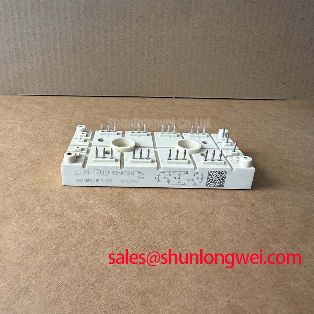
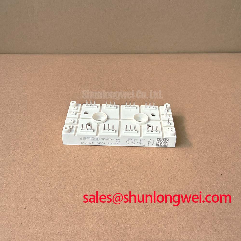
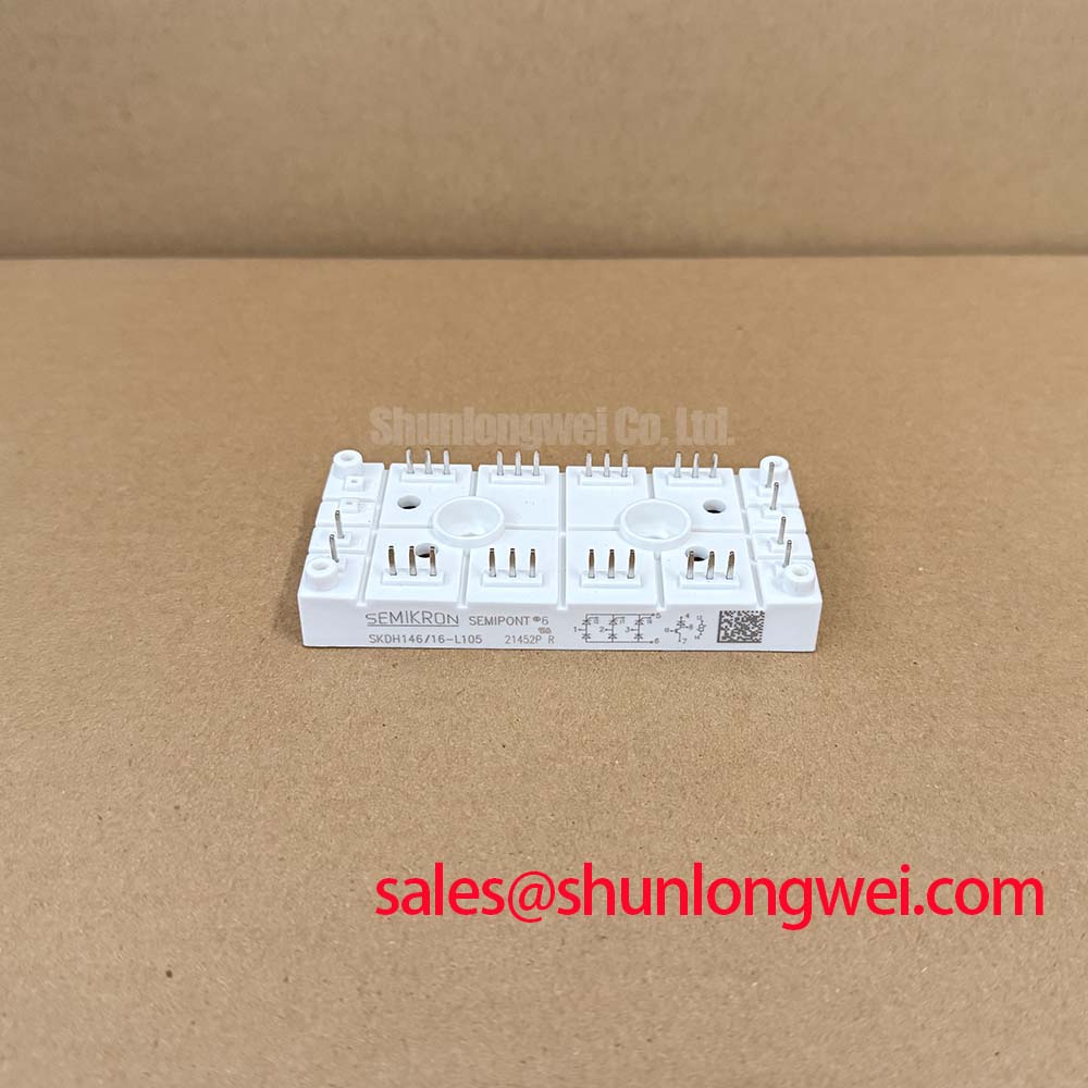
SKD146/16-L105 | Manufacturer: Semikron | Category: Bridge Rectifier Module | Official Specification: 1600 V bridge, 140 A DC output at Ts = 80 °C | IGBT chopper: 1200 V, 90 A at Ts = 80 °C
I check the semiconductor fuse identification and isolate the power terminals before making cold-state diode measurements on the SKD146/16-L105. Parallel charging paths and connected bus capacitors can distort meter readings, so an apparent short needs confirmation with the relevant circuit paths disconnected. Compare conduction direction against the module connection diagram rather than treating one resistance reading as a complete diagnosis.
The official ratings below separate the rectifier bridge from the IGBT chopper. Their voltage and current limits are not interchangeable.
| Parameter | Official Specification | Rating context |
|---|---|---|
| Bridge repetitive peak reverse voltage, VRRM | 1600 V | Rectifier blocking rating |
| DC output current, ID | 140 A | Ts = 80 °C |
| Surge forward current, IFSM | 1250 A | 10 ms surge duration |
| Chopper collector-emitter voltage, VCES | 1200 V | IGBT blocking rating |
| Continuous collector current, IC | 90 A | Ts = 80 °C |
| Isolation voltage, Visol | 2500 V AC | Isolation test rating, not continuous working voltage |
| Junction-to-sink thermal resistance | 0.43 K/W | Per diode |
Design Consideration: coordinate the fuse using its total clearing I²t at the actual circuit voltage and prospective fault current, compared with the semiconductor’s applicable withstand data. The 1250 A at 10 ms surge rating alone does not establish a fuse-clearing energy limit or guarantee damage-free interruption. Initial junction temperature, surge waveform and repeated-event conditions matter.
For the coordination worksheet, record fuse identity, circuit voltage, prospective fault current, clearing I²t and the corresponding semiconductor limit with its test conditions. Check the bridge protection and chopper protection separately; a fuse selected for a diode surge does not establish IGBT short-circuit protection. Review the manufacturer’s product documentation through the Semikron-Danfoss Power Modules Catalog when matching these conditions.
SKD146/16-L105 Thermal-Electrical Optimization: Phase-Controlled Rectification and Firing-Angle Practical Tuning
Trace the AC terminals and DC output connections before changing any controller firing-angle setting. The specified rectifier bridge must not be treated as a phase-controlled thyristor bridge: its diodes do not accept firing-angle commands, and the associated IGBT chopper does not turn them into controlled rectifiers.
Design Consideration: where the surrounding equipment contains a separate controlled converter, its firing-angle transfer characteristics belong to that converter’s topology and operating conditions. Applying a thyristor conversion curve to this module would misrepresent its behavior. Investigate DC-bus ripple, phase-current imbalance and abnormal heating against the actual schematic instead. Power factor and reactive demand depend on the complete input circuit, loading and control arrangement.
The official 140 A bridge rating is specified at Ts = 80 °C. During thermal assessment, establish sink temperature near the mounting interface and evaluate diode losses under the measured load. The 0.43 K/W per-diode value is not a whole-module thermal resistance and cannot describe a short pulse without the relevant transient thermal data.
Engineering Recommendation: when assessing this module within a grid-tied static var compensator or thyristor-switched capacitor assembly, identify its actual subsystem role rather than assuming it performs the main thyristor switching function. For a comparison with SKD110/16, examine circuit configuration, terminal mapping, thermal conditions and mechanical fit before considering interchangeability; a related model name does not establish compatibility.
Assembly Integrity and Layout Architecture: Gate-Pulse Timing for SKD146/16-L105
Identify the chopper’s gate and emitter connections from the connection drawing before attaching a driver or oscilloscope probe. Thyristor firing-pulse rise-time targets, holding current and repeated firing trains are not IGBT gate-drive specifications. Do not transfer those settings to the chopper.
Design Consideration: assess gate-emitter voltage at the device connections while observing collector-emitter switching stress. Keep the gate-drive return path distinct from high-current routing where the documented terminal arrangement permits it; do not assume an auxiliary Kelvin-emitter terminal exists. Evaluate Miller-related gate disturbance against the actual driver circuit, with damping and protection settings determined by switching measurements.
The technical guide Mastering Power System Dynamics explains the relationship between parasitic inductance and switching overshoot. Apply that principle by reducing unnecessary commutation-loop area and validating any snubber against measured stress. The Semikron-Danfoss official hub provides manufacturer resources for device-specific integration guidance.
Field Alert: Use the specified terminal and mounting torques, and establish the approved thermal interface before applying load.
After assembly, check terminal seating, busbar alignment and cable loading without forcing the module connections into position. During controlled commissioning, investigate uneven heating alongside contact condition, phase balance and cooling performance rather than assigning it to a single cause.