


Content last revised on September 10, 2026
LB070WV3-SD03 Inspection and System Compatibility
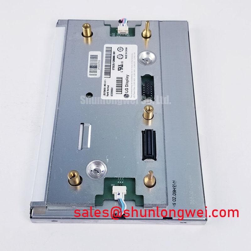
With the host equipment de-energized, inspect the display connector, cable latch, and panel perimeter before applying power to the LB070WV3-SD03; a partially seated signal cable can produce a dark image, unstable colors, or intermittent horizontal artifacts that resemble a panel fault.
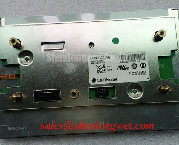
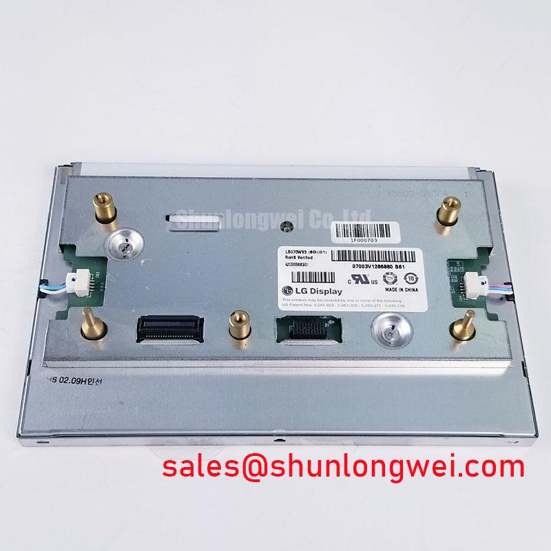
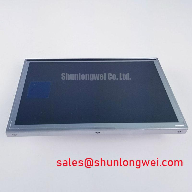
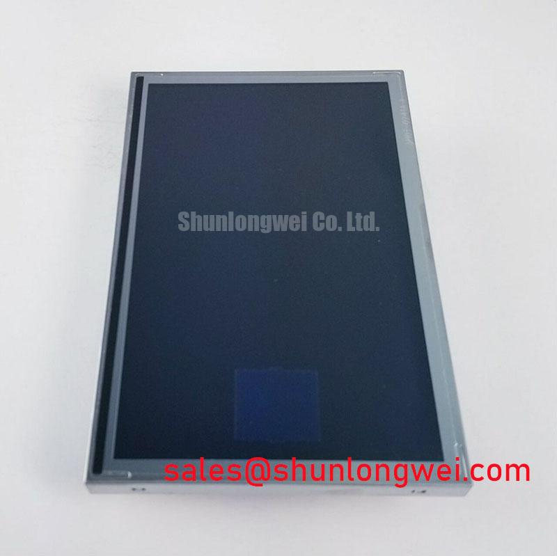
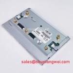
The LB070WV3-SD03 is identified as an Industrial Grade LCD/HMI Panel from LG Display, supplied as a TFT-LCD Display Module. Its official product classification supports evaluation for industrial display repair and HMI replacement work. Interface type, pin assignment, input voltage, timing requirements, optical ratings, mechanical dimensions, and backlight electrical requirements must be verified against the original equipment documentation before installation.
For a marine radar or navigation bridge console repair, treat this module as one part of a larger display assembly. The original controller board, cable harness, bezel retention method, power supply, environmental sealing, and software timing all affect whether a replacement panel can operate correctly. A matching model designation alone does not confirm system-level compatibility.
TTL 24-Bit Digital RGB Bus Synchronization & Logic Power Rail Verification
Before connecting the panel to a host controller, identify the signal architecture from the removed display assembly or the original equipment documentation. The panel designation and official classification do not independently establish whether the installed system uses a TTL RGB bus, LVDS signaling, a proprietary adapter board, or another interface implementation. A technician should inspect the mating connector, flex-cable routing, controller-board markings, and available service documentation before selecting a test method.
When a host platform uses parallel RGB signaling, image data and timing signals must arrive with the correct mapping and sequence. Incorrect color-bit mapping can present as swapped colors, color banding, or unusual image tones. A mismatch between source timing and panel expectations may present as rolling image behavior, a divided image area, missing pixels, or a blank active area despite a functioning backlight. These symptoms are not exclusive to a panel issue; they can also arise from damaged cable conductors, oxidation at contacts, poor ground continuity, or an unstable controller output.
Logic-rail verification should begin at the original display connector with the system documentation in hand. Confirm that the host supply is present only when the equipment’s intended power sequence permits it, then compare the measured rail behavior with the known-good system path where available. The required supply voltage for this panel must be verified from the original panel documentation rather than inferred from another panel family or from connector appearance.
Signal integrity is a Design Consideration during cable replacement or controller-board repair. Controlled routing, a continuous reference path, and secure connector retention help preserve timing relationships between clock and data lines. If split-screen artifacts occur after service, inspect the physical cable first, then compare clock, synchronization, and data activity against a known-good signal path using appropriate test equipment. Do not alter controller timing registers or power sequencing solely to compensate for an unverified panel interface.
⚠️ Field Alert: Disconnect system power and allow stored energy to discharge before removing or reseating the display cable, because live insertion can stress exposed signal contacts and confuse fault isolation.
Surface Anti-Glare and Anti-Reflective Coating for High Ambient Readability
Readability under strong ambient illumination depends on the complete optical stack, not on the LCD module alone. The official classification confirms an industrial-grade TFT-LCD display module, but it does not establish a specific anti-glare treatment, anti-reflective coating, viewing-angle specification, contrast value, or sunlight-readability rating for the LB070WV3-SD03. Those attributes should be confirmed from model-specific factory documentation or from the original equipment assembly.
During bench evaluation, place the panel in the same orientation used by the equipment and inspect it with realistic ambient light. A screen that appears acceptable under indoor workbench lighting can become difficult to read when reflections from windows, overhead luminaires, or bridge-console glazing reach the front surface. Check for broad reflections, haze, uneven brightness, and loss of dark-level detail while displaying a grayscale test image. This process distinguishes surface reflection concerns from source-image problems or backlight irregularity.
TN, IPS, and MVA are panel technologies with different viewing behavior, but the technology of this specific module should not be assumed without the relevant documentation. If an operator reports that colors shift or contrast changes when viewed from an off-axis position, reproduce the observation with the original display configuration. The apparent result can be influenced by polarizer orientation, protective windows, touch overlays, enclosure shadows, and the angle between the observer and the mounting plane.
For equipment evaluated near marine radar and navigation bridge consoles, enclosure sealing and front-window condition are system-level Design Considerations. Salt residue, cleaning chemicals, and scratches on an external protective window can reduce apparent image contrast even when the LCD is functioning normally. Inspect the equipment window separately from the panel surface, and use cleaning methods approved for the installed enclosure materials.
For broader evaluation criteria involving display technologies, optical behavior, and installation factors, consult The Ultimate Guide to Industrial TFT LCD Technology. The guide is useful when comparing the observed image condition with the display system’s original mechanical and optical arrangement.
Constant Luminance Output Control and Backlight Reliability Verification
A dim screen should be separated into active-image and illumination checks before the display module is removed. In a darkened work area, display a known test image and inspect the screen at an oblique angle. A faint active image can indicate that image data is present while the illumination path requires attention. No visible image may point to several different areas, including host power, controller output, cable continuity, panel logic, or the display itself. These observations are starting points for measurement, not single-cause diagnoses.
The official product information provided for the LB070WV3-SD03 does not state the backlight type, backlight supply requirement, dimming method, luminance rating, or rated operational lifetime. Do not assume an LED configuration, PWM dimming frequency, constant-current requirement, or L70 and B50 lifetime target without model-specific documentation. The system integrator should verify the required backlight electrical conditions from the original panel documentation and the host display-driver design.
Where the original equipment includes a separate illumination driver, inspect the driver output, enable control, dimming control, cable continuity, and connector retention in the intended operating state. A backlight that flashes briefly during start-up may indicate a protection response, an enable-sequence concern, a cable issue, or another condition requiring comparison with a known-good assembly. Avoid bypassing protective circuits or forcing an unknown backlight load with an improvised supply.
Heat management is an Engineering Recommendation for any enclosed HMI or navigation-console display. The panel should be retained according to the original mechanical arrangement so that the chassis, brackets, and airflow path continue to perform their intended thermal role. Localized heating near an edge or behind a bezel can affect image uniformity and accelerate degradation elsewhere in the display system. After installation, observe the image during a normal operating period and check whether brightness, color, or flicker changes as the equipment reaches its usual internal temperature.
Constant image quality also depends on the host controller’s dimming behavior. If flicker is visible during low-brightness operation, verify the original dimming control signal and the driver board’s response with suitable instruments. The correction, if required, must be determined by the system design and validated against the original operating conditions rather than selected from a generic panel recommendation.
Suppressing Pixel Jitter and Horizontal White Lines Induced by Adjacent Motor Drives
When pixel jitter, intermittent white lines, or moving image noise appears only while nearby motor equipment operates, begin with a repeatable observation. Record whether the artifact changes with motor speed, load, cable position, display brightness, chassis bonding condition, or operation of another high-power subsystem. A repeatable relationship can guide further testing, but it does not prove that the LCD module itself is defective.
Noise can couple into a display system through shared supply paths, cable routing, connector shields, ground references, or controller-board sensitivity. The correct first action is to inspect the original cable routing and bonding arrangement. Verify that display cables are not pinched, that connector latches are secure, that shielding elements are restored where the original design used them, and that chassis ground paths have not been interrupted during service. Cable substitutions should match the original construction and pinout requirements.
Shield termination and common-mode suppression are Design Considerations controlled by the equipment architecture. A shield connected incorrectly can worsen a noise issue rather than improve it, especially when the display and motor-drive systems use different chassis reference paths. Designers and repair engineers should examine the original grounding scheme, wiring drawings, and measured interference path before changing shield connections or adding suppression components.
Where the controller interface is confirmed and measurement access is available, compare clock and data activity at the source and at the panel-side connector while the disturbance is present. A scope capture may reveal whether the disruption is entering through power, control, or data routing. If the signal path remains stable while the image artifact persists, continue diagnosis through the display controller and panel assembly rather than assigning the cause to cable noise alone.
For potential use in harsh marine radar and navigation bridge consoles, engineers should evaluate enclosure sealing, cable strain relief, chassis bonding, service access, and the original environmental design as a complete system. The LB070WV3-SD03 should be integrated only after its documented electrical and mechanical requirements have been matched to the existing equipment.