
Content last revised on September 12, 2026
Field Diagnostics & Commissioning: Reinforced Insulation Barrier Integrity in SM2G100SH120H3 Topologies
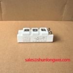
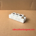
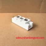
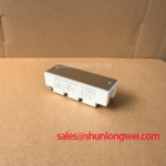
With the equipment isolated and its DC link confirmed discharged, inspect the module mounting area, terminal barriers, gate drive plugs, and adjacent insulation surfaces for conductive dust, moisture tracks, carbon deposits, loosened hardware, or damaged cable jackets. The SM2G100SH120H3 is identified as a Power Semiconductor Module with a General Power Stage topology, so field replacement work should begin by confirming how the existing equipment assigns power terminals, drive connections, sensing paths, and protective earth references.
Reinforced isolation within an inverter assembly is a system level matter involving the gate driver, isolated power supply, connector geometry, PCB spacing, heatsink arrangement, wiring harness, and enclosure contamination condition. Design Consideration: inspect creepage and clearance paths along the actual circuit board and harness route rather than relying only on the visible space around the module. Dust mixed with humid air can turn an apparently clean insulation path into a leakage path, particularly around high impedance gate drive circuits and voltage sensing networks.
During commissioning, monitor the commanded gate signal and the gate reference at the same time. A gate waveform that appears clean at the controller but becomes disturbed at the module connection can indicate common mode coupling, reference movement, poor shielding continuity, connector resistance, or an unsuitable probe connection. Use an isolated measurement method appropriate to the energized circuit and compare the suspect channel with a known stable channel where the machine topology permits.
The isolation withstand level and common mode transient immunity required by a specific drive arrangement must be established from the original equipment documentation and the driver documentation. These values are not stated in the official supplied specifications for SM2G100SH120H3. Do not assign a reinforced isolation rating or common mode transient capability to the module itself without manufacturer documentation. Engineers reviewing gate drive behavior can use this Precision Gate Drive Design reference when checking return paths, gate loop routing, and test setup discipline.
In inverter welder and medium frequency induction heating equipment, cabinet airflow deserves equal attention. Fine metallic dust, process fumes, and condensation can settle on driver boards and insulation barriers long before a module shows visible damage. Inspect cooling passages, clean fan inlets, check that cabinet seals suit the installation environment, and examine whether a cold machine develops condensation after a temperature change. These are maintenance actions, not module specific factory ratings.
⚠️ Maintenance Note: Periodically monitor terminal contact temperature and verify that the cooling air path remains clear before rising thermal stress reaches the power stage.
Transient Dynamics & Electrical Design: Mitigating Hard Switching Transients in SM2G100SH120H3 Assemblies
Capture collector to emitter voltage, gate to emitter voltage, and load current together during the hard switching event to determine whether the observed stress occurs during turn on, turn off, freewheel commutation, or a protection response. The supplied official data defines SM2G100SH120H3 as a module for a general power stage, but does not provide switching energy, short circuit withstand time, gate voltage limits, or voltage and current ratings. System operating limits must therefore remain tied to the original machine design and approved technical documentation.
Hard switching transient control depends heavily on physical loop geometry. Design Consideration: keep the commutation path compact, maintain low impedance bus connections, and avoid routing gate wiring alongside high current switching conductors. Parasitic inductance can add voltage overshoot during current interruption, while common mode movement can disturb the gate reference. Oscilloscope results should be reviewed with probe placement in mind because a long ground lead can add ringing that is not present at the device terminals.
Short circuit protection should be examined as a coordinated function of the controller, gate driver, current sensing circuit, fault communication path, and turn off behavior. A driver may use desaturation detection, current measurement, or another machine specific method to identify a fault. Where the original design applies staged turn off behavior, retain the intended sequence and validate it under controlled conditions. A rapid uncontrolled gate removal can create a high inductive voltage transient, while an excessively delayed response can increase device stress. The proper timing is system determined and must be verified against the installed power circuit.
Parallel module arrangements need separate attention. Static current distribution can be influenced by the temperature behavior of collector to emitter saturation voltage, but this does not guarantee dynamic current balance. Equal electrical path length, symmetrical busbar geometry, comparable gate loop impedance, and coordinated driver timing are Design Considerations for reducing imbalance. Measure each branch current where practical rather than assuming that physically similar modules receive identical switching stress.
Regenerative energy handling also belongs in the transient review. In welding systems or induction heating power supplies, a decelerating load or changing resonant condition can return energy to the DC link. Confirm the condition of the braking chopper circuit, braking resistor connections, bus capacitors, and control logic before attributing a DC link overvoltage event to the power module. Discoloration around resistor terminals, loose busbar joints, and degraded capacitor connections can all alter the transient response of the assembly.
For contextual comparison, the switching behavior of a power semiconductor differs from the output behavior of an isolated solid state switching device. The operating concepts described in this Solid State Relay working principles reference can help maintenance teams separate load switching discussions from inverter gate drive and commutation analysis.
Benchtop Waveform Tuning: Mitigating Stress via Transmission Line Impedance Mismatch on SM2G100SH120H3
Probe the module terminal waveform and the remote load side waveform during a controlled switching test when a long output lead is suspected of producing ringing or reflected voltage. Cable impedance mismatch can cause the waveform at a remote motor, transformer, or induction coil connection to differ substantially from the waveform measured at the inverter output. The amplitude and duration depend on cable construction, lead length, load characteristics, switching edge behavior, grounding arrangement, and the condition of termination components.
Do not treat a ringing trace as proof of a single fault. It may indicate a transmission line effect, but it can also reflect unsuitable probing, a floating reference, a damaged output cable, a loose lug, an incorrect filter connection, or a change in the load circuit. Compare the measurement with the known operating waveform for the specific equipment whenever that reference is available. Inspect output terminals for heat discoloration and check that cable shields, bonding straps, and return conductors follow the original routing.
Design Consideration: output chokes and voltage rate limiting filters can be evaluated when the measured waveform shows stress at the remote load or at the inverter terminals. Their selection cannot be assigned from the module designation alone. The system engineer must assess load current, switching frequency, cable characteristics, insulation requirements, resonant behavior, thermal capability, and measured peak voltage before finalizing a filter arrangement.
Gate drive tuning should also be performed only with the machine protection functions active and measurement points established. Changes in gate resistance, drive voltage, or turn off behavior can change switching losses, voltage overshoot, electromagnetic noise, and current sharing. These adjustments are Engineering Recommendations for controlled bench validation, not factory settings for SM2G100SH120H3. Preserve the original gate drive circuit values until waveform evidence supports a controlled change.
For industrial inverter welders, inspect the output conductors between the power section and welding transformer connections. For medium frequency induction heating units, inspect the conductors between the inverter and resonant tank, including flexible links, water cooled connections where used by the equipment, and protective bonding. Loose or oxidized joints can add impedance and heat, which may alter the observed waveform and reduce repeatability during testing.
Thermal inspection should accompany waveform review. A connection that heats faster than similar parallel connections may warrant torque verification, surface cleaning, and examination of the contact interface. General Industry Design Consideration: use the equipment manufacturer’s fastening requirements for each terminal and heatsink attachment, because the official supplied information for this module does not specify mounting screw size or torque.
SM2G100SH120H3 Circuit Protection & Reliability: Calibrating Multi Module Parallel Current Sharing
Measure branch current and gate waveform timing across each parallel position while the power stage operates at a controlled load, then compare the traces for consistent turn on and turn off behavior. In a multi module assembly, steady state current sharing can be influenced by the positive temperature coefficient associated with collector to emitter saturation voltage in some operating regions, yet the complete result remains dependent on module matching, thermal conditions, conductor resistance, busbar symmetry, and gate drive layout.
Dynamic imbalance often becomes visible before a static measurement suggests a problem. One branch can switch earlier, receive a different gate reference, see a different stray inductance, or operate at a different temperature because of uneven heatsink contact. Investigate the complete path from gate driver output through the connector and return conductor to the module interface. Do not adjust a single channel in isolation without checking whether that adjustment shifts stress to the other branches.
Protection calibration should preserve coordination among overcurrent detection, gate blocking, fault latching, controller shutdown, and restart behavior. A recurring fault after replacement may originate in sensing circuits, driver supply stability, interlock wiring, cooling performance, or the load itself. Review fault records where the equipment provides them, inspect current transformer and shunt connections, and verify that gate driver supply rails remain stable during the event. This method avoids treating the module as the only possible source of an inverter shutdown.
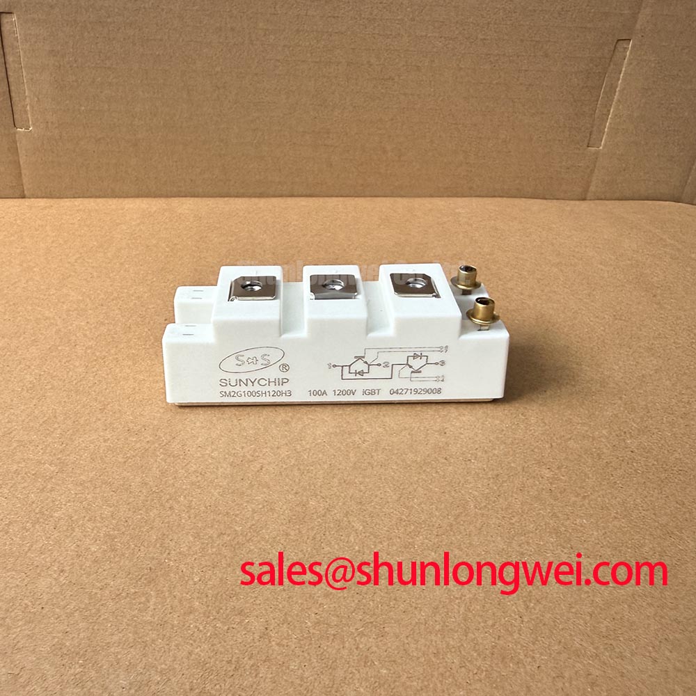
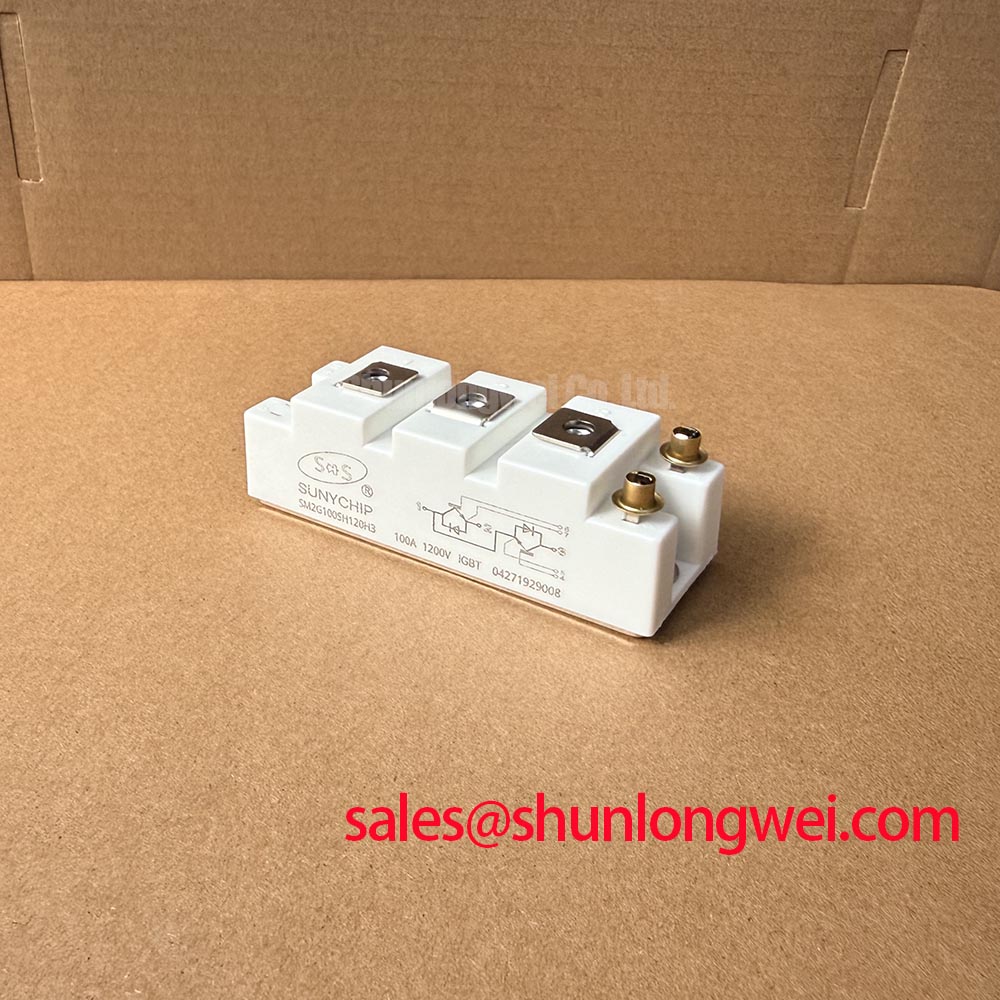
The SM2G100SH120H3 is identified in the supplied product information as a Standard series Module. Voltage capability, current capability, switching limits, thermal resistance, isolation ratings, and pin assignment are not included in the supplied official specifications. When integrating this unit into an existing repair or evaluation process, the system integrator should verify the required electrical ratings, terminal arrangement, driver conditions, and mechanical interface from the original equipment documentation.
Preventive maintenance should include cleaning heatsink fins, checking fan operation, examining thermal interface material for drying or displacement, and inspecting terminal tightness during scheduled outages. Use temperature trending to identify developing contact resistance or blocked airflow. In humid industrial environments, examine the enclosure for condensation paths and confirm that equipment warm up procedures keep moisture away from insulation surfaces and low level control circuits.