

Content last revised on October 19, 2026
TIM1200DDM17-TSA000 Thermal-Electrical Optimization: Semiconductor Fuse I2t Coordination
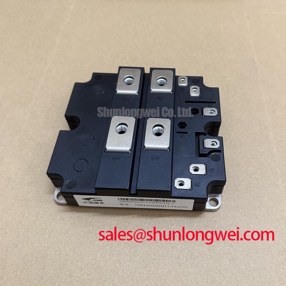
Verify the equipment nameplate and isolated power connections before assessing TIM1200DDM17-TSA000. Manufacturer: Toshiba | Category: IGBT Module | Official Specification: VCES 1700 V; continuous IC 1200 A at Tc = 80 °C; Tj,max 150 °C; typical junction-to-case thermal resistance per IGBT 0.018 K/W.
I start a fuse-coordination review by checking the installed fuse designation against the protection drawing and tracing every source feeding the faulted branch. For the Toshiba TIM1200DDM17-TSA000, the practical question is how the complete protection chain interrupts fault energy. A fuse selection based only on the module’s continuous current rating leaves capacitor discharge, supply contribution, and gate-driver response outside the assessment.
Design Consideration: Compare the fuse manufacturer’s total clearing I²t and peak let-through current with the equipment’s validated protection limits at the actual circuit voltage and prospective fault current. Pre-arcing I²t describes the melting stage; total clearing I²t includes the subsequent interruption interval. These quantities serve different purposes when evaluating semiconductor protection. An IGBT short-circuit withstand specification also has operating conditions and cannot automatically be treated as a fuse-compatible I²t rating.
The protection review should distinguish a gate-controlled short circuit from a fault that persists after gate turn-off. Desaturation protection addresses the first event through the driver, while fuses and upstream interruption equipment address fault paths that remain electrically connected. Prevention of enclosure rupture requires system-level coordination and validation; the 1700 V blocking rating alone establishes no containment guarantee. Record which protective element acts first for each credible fault path.
Inspect fuse holders, busbar joints, and cable terminations for changes that could alter the intended current path. Evaluate conductor spacing against working voltage, contamination, and the equipment’s insulation design rather than adopting a generic clearance. Keep fault-current loops compact where the assembly permits, while preserving access for inspection and the clearances specified by the equipment designer. After an interruption, inspect associated connections before fitting another fuse.
A MOV network belongs in the same schematic review when it forms part of the converter’s overvoltage protection. Its clamping behavior, pulse-energy capability, and coordination with upstream protection should be evaluated against the actual disturbance. Lead inductance and connection placement affect the voltage reaching the protected circuit. A MOV cannot be assumed to control local IGBT switching overshoot, so compare measurements at the module terminals with those at the suppression network.
Where another controlled power stage is present, the FF650R17IE4P can be reviewed as a separate IGBT-module reference within the system assessment. Its role must follow the circuit topology; an IGBT module should not be assigned the function of a passive input rectifier simply because it appears in a related power assembly.
Assembly Integrity & Layout Architecture: Implementing Prevention of Ceramic Substrate Rupture During Operation for TIM1200DDM17-TSA000
Check the heatsink contact surface and module mounting condition before tightening the assembly. Residual interface compound, raised burrs, embedded particles, and distorted mounting surfaces can prevent uniform seating. As a maintenance practice, I document the removed interface pattern before cleaning because uneven transfer can help locate contact problems. That pattern supports inspection; it does not by itself establish the cause of a thermal fault.
Engineering Recommendation: Assess baseplate curvature and heatsink flatness using the applicable mechanical drawing and assembly procedure. Avoid forcing a module against an unsuitable surface through additional screw load. Bring the mounting points into contact progressively, then use the specified tightening sequence and a calibrated torque tool. Where the approved procedure calls for a diagonal sequence, follow it consistently and record completion. Mounting screw torque and electrical terminal torque require their respective specifications.
Thermal interface material should fill surface irregularities without introducing an unnecessarily resistive layer. Select its application method and assembled thickness from the approved module, heatsink, and compound requirements. Inspect for coverage discontinuities and trapped contamination during assembly qualification. A universal paste thickness would overlook differences in flatness, curvature, compound behavior, and mounting pressure, so the installation drawing should control the finished interface.
Electrical protection deserves review before the newly assembled module returns to service. Desaturation monitoring observes collector-emitter voltage during commanded conduction, using a driver-defined threshold and timing sequence. Turn-on blanking, sensing-network response, fault processing, and gate discharge all contribute to the protection interval. Set these against the applicable short-circuit operating conditions and confirm the behavior at the power terminals. A detection-delay target in isolation does not establish successful protection.
A driver with two-stage soft turn-off can shape gate discharge during fault interruption, subject to validation of voltage overshoot and energy dissipation. The relevant measurements include collector-emitter voltage, gate-emitter voltage, and fault current during the same event. Probe placement matters: shared wiring inductance and measurement-loop pickup can obscure the voltage actually applied to the gate. Protection evaluation should therefore include the installed connection geometry.
On a driver using an optocoupler or digital isolator, compare the isolator’s common-mode transient immunity with measured switching conditions. Check local supply behavior, return paths, and separation between sensitive signals and power conductors. Common-mode disturbances can contribute to unexpected driver behavior, but an isolated fault indication requires investigation across the sensing circuit, power supply, and control path before assigning a cause.
TIM1200DDM17-TSA000 Thermal-Electrical Optimization: Drop-In Retrofit: Turn-On/Turn-Off Tuning
Compare the existing gate-driver circuit with the proposed module connection before retaining its turn-on and turn-off resistors. For TIM1200DDM17-TSA000, matching the headline voltage and current is only part of a replacement assessment. Terminal arrangement, mounting geometry, driver loading, switching behavior, and protection compatibility determine whether the existing assembly can support the installation. Keep the comparison tied to the complete part designation.
Design Consideration: Adjust external turn-on and turn-off resistance through controlled switching measurements within the approved operating envelope. Increasing gate resistance generally slows the affected transition, changing the balance between switching loss, current slew rate, voltage overshoot, and ringing. The response also depends on driver impedance, circuit inductance, and the commutating device. Choose the final values from observed performance across the intended operating conditions.
Separate turn-on and turn-off paths can provide independent adjustment where the driver architecture supports them. Confirm the direction and condition of any steering components before attributing a waveform change to resistance alone. Inspect the gate connection and its return conductor for unnecessary loop area, loose contacts, or routing near high-current switching paths. Preserve the terminal assignments shown in the module documentation without assuming an additional dedicated emitter connection.
During testing, distinguish sustained oscillation from probe-induced ringing by reviewing the measurement arrangement and repeating the observation with an appropriate low-inductance connection. Compare gate and collector-emitter behavior during the same transition. A larger resistor may reduce one visible symptom while increasing switching energy, so retain the waveform records alongside the corresponding current, temperature, and driver conditions. This gives maintenance staff a usable baseline after commissioning.
The linked SKKE 120F17 belongs in a rectifier-function review, rather than a verified direct-replacement list for this IGBT module. Rectifier and controlled-switch functions require different selection criteria. A replacement decision must establish circuit function, electrical limits, connections, cooling interface, and mechanical fit; a shared voltage class cannot establish interchangeability.
For compatibility assessment, engineers may evaluate this module for a multi-megawatt offshore or onshore wind turbine full-scale converter, subject to the converter’s topology, cooling arrangement, and protection requirements. This is an application evaluation rather than a statement of approved fit. Procurement should retain the full TIM1200DDM17-TSA000 designation and equipment revision so engineering can resolve interface differences before installation.
Assembly Integrity & Layout Architecture: Implementing Thermal Paste Degradation Prevention for TIM1200DDM17-TSA000
Trend case temperature against load and cooling conditions before deciding that the thermal interface needs replacement. A rise can reflect restricted airflow, changes in coolant performance, connection heating, or interface deterioration. Compare measurements at repeatable locations under comparable operating conditions. I use those records to decide where inspection should begin and to avoid unnecessary removal of a correctly seated module.
The official typical junction-to-case thermal resistance is 0.018 K/W per IGBT. It describes a thermal path inside the module boundary, excluding the external interface and heatsink. The 150 °C maximum junction temperature is a limit rather than a maintenance target. For transient loading, the distinction between steady thermal resistance and time-dependent thermal response matters; the Foster and Cauer thermal-network explanation provides background on thermal impedance, while module-specific modeling requires the applicable thermal data.
Engineering Recommendation: During planned shutdowns, inspect cooling passages, fan condition where applicable, terminal discoloration, and accessible interface edges. Establish inspection intervals from operating exposure, contamination, thermal trends, and the equipment maintenance plan. When interface renewal is justified, remove the old material without damaging mating surfaces, inspect contact geometry, and apply the approved compound using a repeatable process. Avoid compensating for a mechanical seating defect with excess paste.
Maintenance Note: Monitor connection temperature trends and check cooling-path cleanliness during scheduled maintenance before increasing load after service. Where terminal checks are required, use the approved torque procedure and distinguish inspection from repeated tightening. Record disturbed connections and complete the specified reassembly checks. In environments with temperature changes, inspect for moisture ingress and condensation before re-energization, following the cabinet’s environmental control procedure.
For an integration involving repeated charge and discharge loading, assess measured temperature excursions alongside the cooling response and operating sequence. Reducing avoidable thermal excursions may support a less demanding operating profile, but it does not establish a numerical lifetime extension. Keep the evaluation focused on the module’s actual load history and permitted temperature boundaries. The Power Electronics Masterclass offers broader selection and troubleshooting context for this assessment.
After interface work, record the compound identification, application method, mounting sequence, and inspection results. Compare the subsequent temperature trend with the pre-service baseline at comparable load and cooling conditions. If the rise persists, continue through the cooling circuit and electrical connections before reopening the module interface. Close the maintenance record with the measured operating conditions and the checks needed at the next scheduled inspection.