


Content last revised on October 1, 2026
Preventing Spurious Faults: Gate Return Routing Checks for TSR100AA60
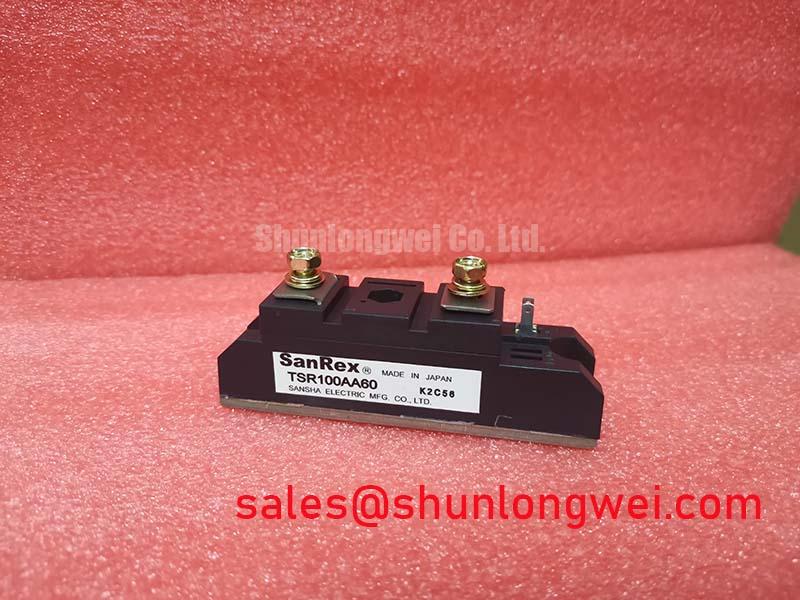
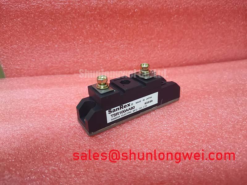
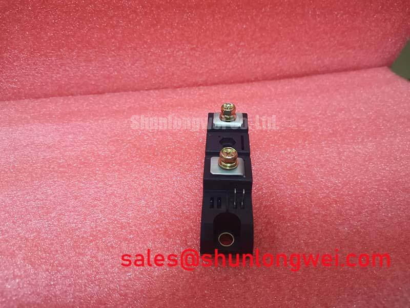
Trace each control lead from the installed TSR100AA60 to its driver and compare the terminal markings with the equipment schematic when unexplained trips appear. A gate and auxiliary emitter return are relevant only if the confirmed device topology provides those terminals. Do not treat the model name or its Module package as proof of an IGBT, a Kelvin emitter or a particular pinout.
If the circuit uses a separately routed control return, keep its path distinct from the main load-current path where the documented terminal arrangement permits. This is a Design Consideration: current flowing through shared wiring impedance can disturb the voltage seen by a control circuit. Check the return route at the driver connector as well as at the module, then compare control waveforms at both ends during the fault event. Oscillation or a transient at one measurement point is a reason to inspect the complete loop, not grounds to assign a single cause.
Check conductor spacing against the equipment’s insulation design and inspect cable support, connector seating and any disturbance introduced by a recent repair. Clearance cannot be assigned from the supplied product information. A proposed negative turn-off bias likewise belongs to the verified driver and device design; measure common-mode disturbance at the installed circuit before changing it.
TSR100AA60 Thermal-Electrical Optimization: Checking Overcurrent Protection Against the Actual Topology
Capture load current and the protection response during a repeatable trip, then identify the installed semiconductor topology before interpreting the trace as a short-circuit event. An SCSOA limit, a type-I or type-II short-circuit classification, a detection interval and a two-stage soft turn-off sequence are not specified for TSR100AA60. Applying an assumed IGBT protection timing to this module would leave the most important comparison unverified.
For an equipment-level protection review, follow the fault signal from the sensor through the controller to the switching command. Check whether the response limits current without producing an excessive voltage transient at the module terminals. This is a Design Consideration, and the acceptable response must come from the confirmed device limits and measured system conditions. Where the circuit contains a commutating diode, examine its recovery waveform alongside the switch-node voltage before evaluating a snubber change. Neither a diode nor its recovery behavior is established by the supplied TSR100AA60 specification.
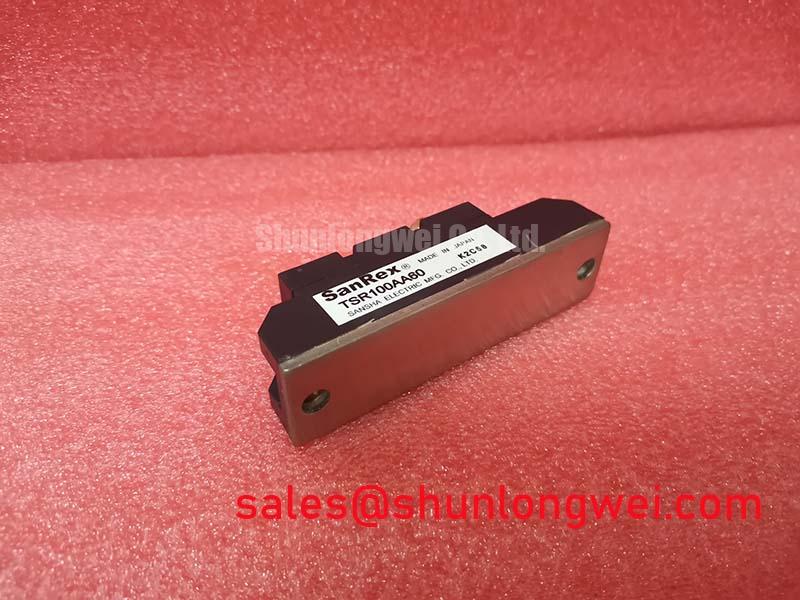
Inspect the heatsink contact surface and cooling path while the assembly is accessible. A rising case or contact temperature under comparable loads calls for checks of airflow, mounting condition and thermal-interface condition; it does not, by itself, identify an internal module fault. Thermal cycling can also affect dissimilar materials in an assembly through differences in thermal expansion. Record temperatures at consistent measurement points so later inspections can be compared meaningfully.
Transient Dynamics & Electrical Design: Current Distribution Checks for TSR100AA60
Measure the current in each parallel path during both steady load and switching transitions if TSR100AA60 operates in a parallel assembly. Unequal steady-state current and unequal transient current are separate observations: inspect connection resistance, busbar geometry and cooling contact for the former, then compare control-path wiring and switching waveforms for the latter.
A positive temperature coefficient of on-state voltage can assist static current sharing in some semiconductor operating regions, but that characteristic is not established for this model. Do not use it to justify parallel operation without the confirmed device characteristic and operating conditions. Symmetrical power and control routing is an Engineering Recommendation when parallel switching paths are present; verify its effect with measurements rather than assuming visually similar wires have equal impedance.
Inspect terminal condition and tightening records against the equipment’s approved assembly instructions. Also review clearance at nearby conductors after any busbar change: a mechanically convenient route is not necessarily compatible with the installation’s insulation requirements. For a broader framework for reviewing switching stress and thermal margins, the Power Electronics Masterclass provides background; the module’s own limits still govern any product-specific decision.
Benchtop Waveform Tuning: Managing Thermal Stress in a Bidirectional System Using TSR100AA60
Log module terminal voltage, path current and heatsink temperature through a representative charge-to-discharge transition before changing control settings. In a micro-grid storage converter, bidirectional power flow is a possible system operating condition, not a documented capability of TSR100AA60. Confirm the module’s circuit role and permitted current direction from the original equipment schematic before assessing it for that service. The same compatibility check applies to a commercial string inverter repair.
Compare temperature rise during sustained operation with the rise following short load peaks. A transient thermal-impedance network can support a peak junction-temperature assessment only when the relevant device data, initial temperature and pulse history are known; none of those limits is supplied here. Use measured waveforms to identify the actual stress interval, and leave the allowable margin to the confirmed specification and system validation.
Where the equipment uses controlled rectification, review firing commands and measured input current before attributing grid harmonics to the module. Where it uses a semiconductor fuse, compare the fuse’s documented energy-let-through characteristic with the device’s confirmed fault capability and the installation’s protection study. Neither rectifier firing behavior nor a fuse coordination limit is a stated TSR100AA60 product rating.
Maintenance note: Isolate the equipment before inspecting module terminals, and check heatsink cleanliness and thermal-contact temperature trends during scheduled maintenance. Record condensation or moisture near the assembly and correct enclosure or airflow conditions through the equipment maintenance procedure. Finish the bench check by saving the voltage, current and temperature traces with the load state and cooling conditions; those records make a later change in switching or thermal behavior observable.