

Content last revised on October 21, 2026
V300B12H250BL Operational Boundaries: Preventing Terminal Overheating
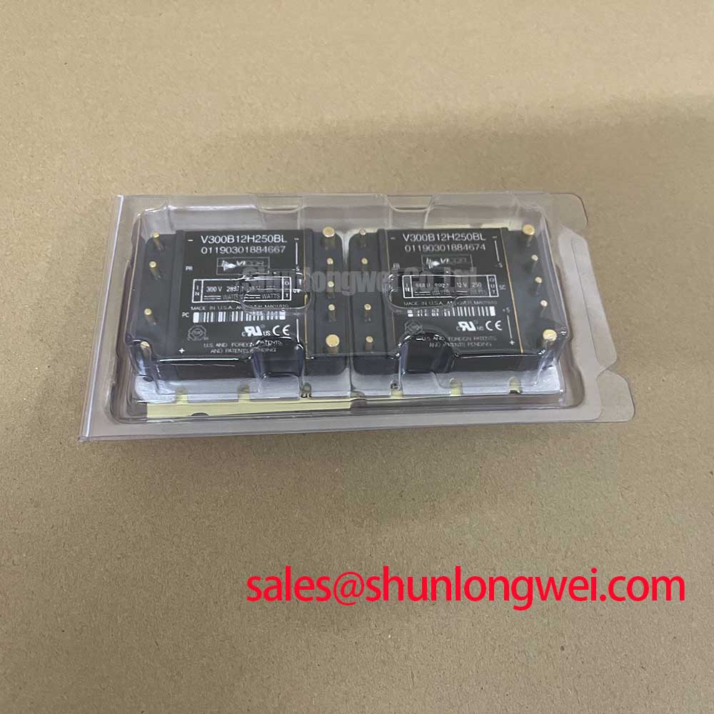
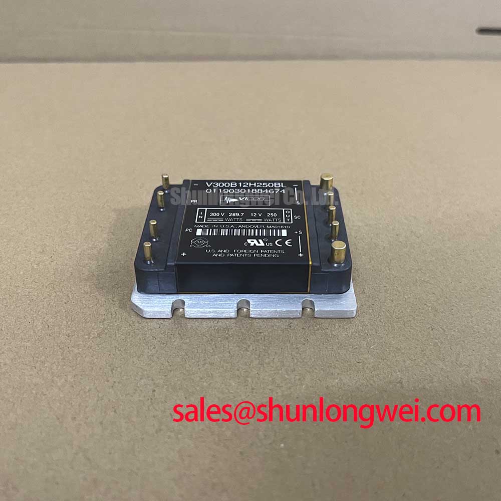
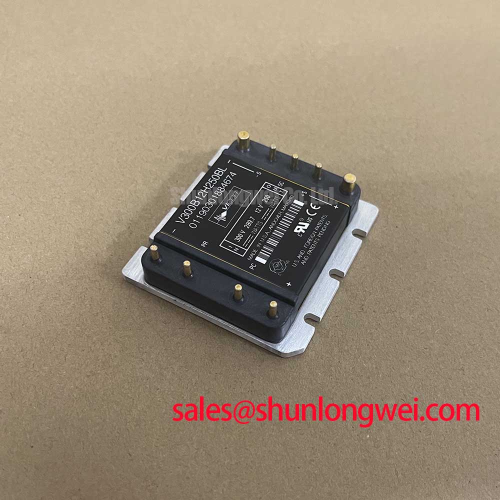
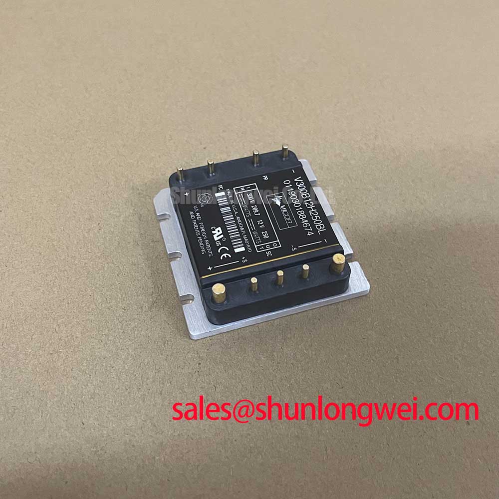
Check the unpowered assembly first by confirming the marked input and output terminals, then compare cold-state continuity and insulation readings with a known-good installation before applying DC power. The Vicor V300B12H250BL is specified for a 300 VDC nominal input, a 180–375 VDC input range, and a regulated 12 VDC, 250 W output. Its published efficiency is up to 88%, with 3000 Vrms input-to-output dielectric withstand and a baseplate operating range of −40°C to 100°C.
Terminal heating should be investigated through the complete bolted-current path rather than by judging the converter from its output voltage alone. With the DC supply isolated, inspect the mating surfaces, fastener seating, conductor compression, and signs of localized discoloration. A micro-ohmmeter can be used to audit the assembled joint; a site acceptance plan may use a low-micro-ohm contact-resistance limit, but that limit is a Design Consideration, not an official V300B12H250BL specification.
Apply current gradually during commissioning and record the terminal and baseplate temperature profile with thermography. A rising hotspot at one connection suggests that the joint, conductor termination, or current distribution requires closer inspection. Keep high-current conductors short and mechanically supported, while separating heat-sensitive control wiring from the power path. For a heavy-duty variable-frequency AC motor drive, designers should verify the converter’s 250 W output against the actual control, gate-drive, sensing, and auxiliary loads over the full input range.
The compact Mini package measures 57.9 × 55.9 × 12.7 mm. Its restricted height can simplify cabinet integration, but the surrounding enclosure still needs an airflow and heat-spreading review. The stated efficiency is an official maximum value; actual thermal performance depends on load, input voltage, mounting, and ambient conditions.
V300B12H250BL Circuit Protection & Reliability: DC High-Potential Insulation Testing
Before connecting the converter to a high-voltage bus, isolate every external circuit and measure terminal-to-baseplate insulation with an appropriate insulation tester. A maintenance procedure may define a Design Consideration such as 500 MΩ or greater at 2.5 kV DC, but this test level must be approved for the installed assembly and must not be treated as an official product rating. High-potential testing can damage connected controls, sensors, or suppression components if they remain in circuit.
| Parameter | V300B12H250BL Official Specification | Integration Relevance |
|---|---|---|
| Nominal input | 300 VDC | Confirm bus compatibility |
| Input range | 180–375 VDC | Check transient and low-line conditions |
| Output | 12 VDC, 250 W | Audit continuous and transient load demand |
| Isolation withstand | 3000 Vrms input to output | Maintain system insulation coordination |
| Package | 57.9 × 55.9 × 12.7 mm | Verify enclosure and heatsinking clearance |
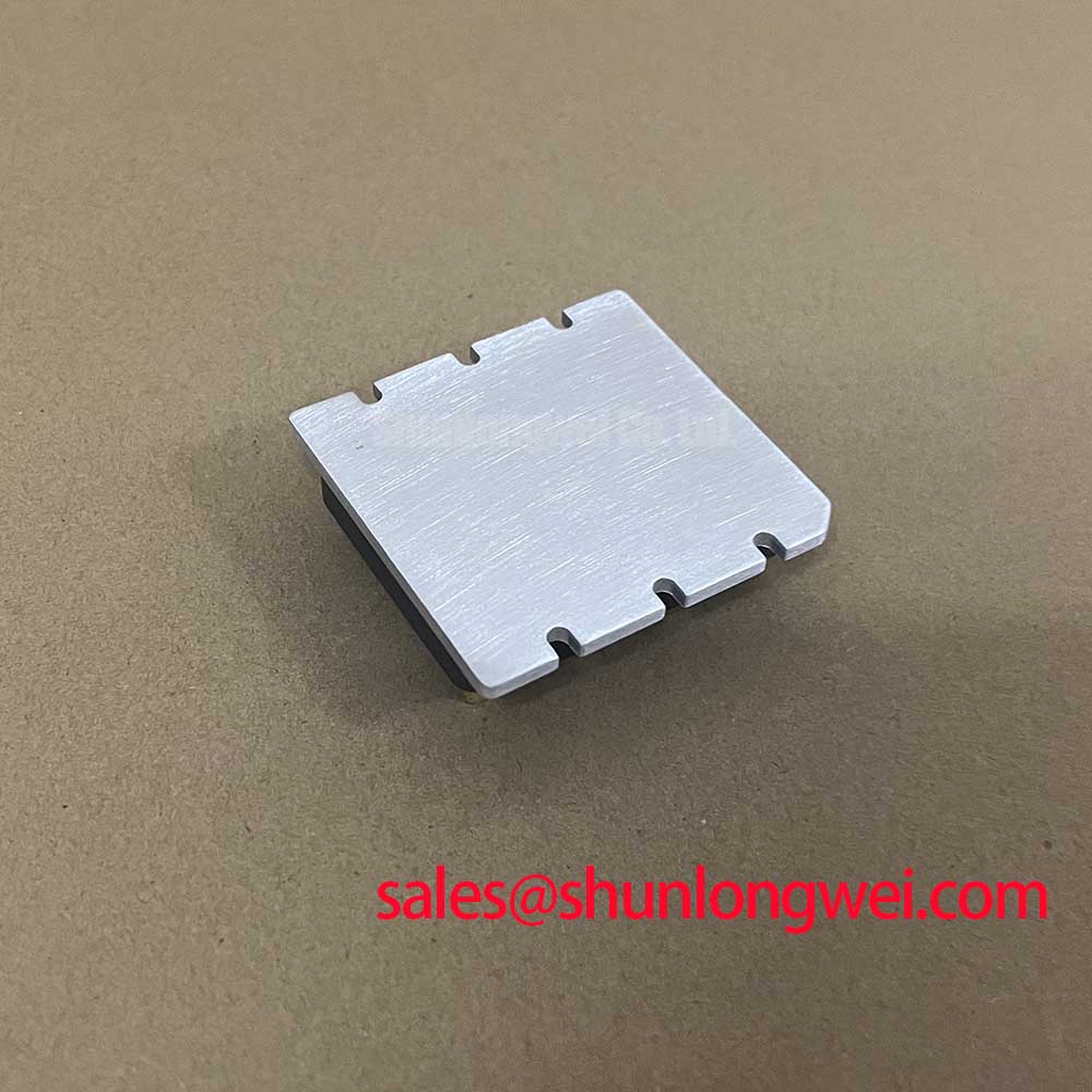
Thermal interface material should be applied as a uniform, thin layer suited to the mating surfaces. A 50–80 µm application is a Design Consideration for controlled interface assembly, not a Vicor factory parameter. Tighten mounting points progressively in a cross-pattern so the baseplate is not distorted. The final torque is system-dependent and should follow the approved mechanical drawing and fastener specification. Dielectric-strength principles and breakdown testing are discussed in Dielectric Strength and High-Voltage Breakdown Testing.
💡 Bench Tip: Use ESD protection and record the cold-state insulation baseline before repeating any powered or high-potential test.
Field Diagnostics & Commissioning: Short-Circuit Energy Let-Through Matching in V300B12H250BL Topologies
Protection coordination must match the DC bus, wiring inductance, fuse clearing behavior, and converter installation. Selective high-speed semiconductor fusing is a Design Consideration; the fuse total-clearing I²t must be evaluated against the converter’s documented short-circuit and transient limits rather than inferred from the 250 W output rating.
During commissioning, verify fuse installation, polarity, busbar spacing, and the physical distance between the protection device and converter terminals. A current probe and oscilloscope can reveal whether a fault is interrupted cleanly or whether wiring inductance produces excessive overshoot before clearing. Do not reuse a fuse after a high-energy event merely because the visible body appears intact. For related front-end power-path evaluation, engineers may review the system context of VI-252-EU. The VI-2W4-CV can also be examined as a separate Vicor reference device, subject to its own specifications and mechanical compatibility.
V300B12H250BL Operational Boundaries: Evaluating Negative Gate Bias vs Active Miller Clamp Limits
The V300B12H250BL is a DC-DC converter, so negative gate bias and active Miller clamping belong to an associated switching stage rather than to an official specification of this converter. In a variable-frequency drive power architecture, the gate-driver designer should control the turn-on and turn-off loop inductance, dead time, and common-source or return-path impedance to reduce cross-conduction risk. Any negative bias, such as a proposed −5 V to −15 V range, is a Typical Starting Point only when supported by the selected semiconductor and gate-driver documentation.
Measure the switching node and gate waveform at the device pins, not at a remote controller header. Miller-induced displacement current can create false turn-on when the opposing switch changes state rapidly; an active clamp may reduce that effect when its voltage, current, timing, and layout are validated for the selected switch. The power-stage engineer should also examine diode reverse-recovery behavior, bootstrap capacitor recharge, and dead-time interaction as a combined system problem. The technical reference Evolution of Negative Off-Bias Gate Drive Circuits provides additional background for this design topic.
For repair work, confirm that the replacement converter’s input range, isolated output, package envelope, and thermal mounting conditions match the original equipment documentation before energizing the drive cabinet.