


Content last revised on March 3, 2026
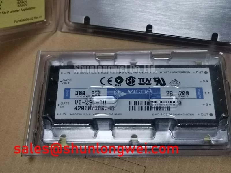
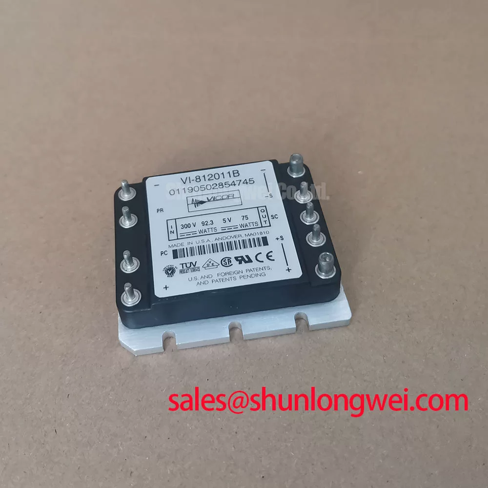
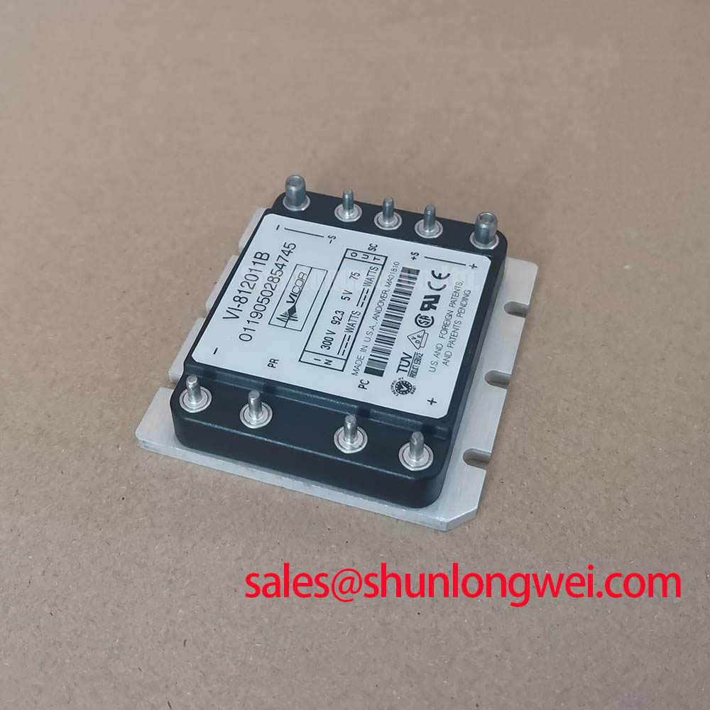
Vicor VI-812011B High-Efficiency 24V to 5V 150W DC-DC Converter
The Vicor VI-812011B is a high-performance, modular DC-DC converter designed to provide a stable 5V DC output from a nominal 24V DC input rail. Leveraging Vicor’s proprietary Zero-Current Switching (ZCS) technology, this module achieves exceptional power density and thermal efficiency, making it a staple for engineers designing distributed power architectures. For systems requiring high-reliability logic power from industrial buses, the 150W VI-812011B provides a deterministic power solution that minimizes electromagnetic interference (EMI) and heat dissipation challenges.
UVP Statement: Delivering high-density 150W conversion through ZCS architecture to eliminate switching losses in 24V industrial power rails.
- Top Specs: 24V Input | 5V Output | 150W Power Rating
- Key Benefits: Reduced heatsink requirements; superior EMI profile.
- Primary Application Solution: How does the VI-812011B handle industrial noise? Its ZCS topology inherently minimizes high-frequency switching noise, simplifying filter design for sensitive logic circuits.
For 24V industrial rails requiring low-noise 5V logic power at high density, the 150W VI-812011B is the optimal choice.
Key Parameter Overview
Decoding the Specs for Enhanced System Efficiency
The technical performance of the VI-812011B is defined by its ability to maintain high efficiency across a wide load range. Unlike traditional PWM converters, the modular nature of this Vicor component allows for easy paralleling and integration into custom power plates. The following data highlights the critical operating boundaries for engineering evaluation:
| Technical Parameter | Specified Value | Engineering Significance |
|---|---|---|
| Input Voltage (Nominal) | 24V DC | Standard industrial bus compatibility |
| Output Voltage | 5V DC | Optimized for TTL/CMOS logic and microprocessors |
| Output Power | 150W | High current capability for dense logic arrays |
| Switching Technology | Zero-Current Switching (ZCS) | Drastic reduction in switching losses and EMI |
| Isolation Voltage | 3000Vrms | Ensures safety and prevents ground loops |
| Package Style | VI-200 Series Full-Brick | Proven mechanical footprint for rugged environments |
Application Scenarios & Value
Achieving System-Level Benefits in High-Density Power Conversion
In modern industrial automation, engineers often face the challenge of deriving low-voltage logic power from a noisy 24V bus without introducing significant heat or bulk. The VI-812011B addresses this through its modular form factor and high-frequency operation. A typical application scenario involves high-speed PLC (Programmable Logic Controller) racks where space is at a premium and cooling is restricted. By utilizing the 150W output of this Vicor module, designers can consolidate multiple point-of-load converters into a single, highly reliable source.
The ZCS architecture can be compared to a swing: traditional converters "push" the swing regardless of its position, wasting energy and causing stress (switching losses). The VI-812011B only "pushes" when the swing reaches its peak (zero current), ensuring the most efficient energy transfer with minimal friction. This makes it ideal for robotic servo drives and distributed control systems where thermal management is a primary constraint.
While this module is ideal for 150W logic loads, systems requiring much higher current handling in the power stage might integrate related components like the SKM300GA123D for the high-voltage inverter section. Integrating the VI-812011B ensures that the control logic remains isolated and clean, even when the power stage is switching heavy inductive loads.
Industry Insights & Strategic Advantage
The Strategic Shift Toward Modular Power in Industry 4.0
The landscape of power electronics is shifting away from centralized, "one-size-fits-all" power supplies toward decentralized, modular architectures. The VI-812011B represents this strategic trend by providing a "power building block" that allows for rapid scaling and increased MTBF (Mean Time Between Failures). By moving the conversion process closer to the load, engineers can reduce resistive losses in long DC cable runs, a critical factor in large-scale high-efficiency power systems.
Furthermore, as industrial standards like IEC 61800-3 become more stringent regarding conducted and radiated emissions, the ZCS technology in the Vicor module provides a proactive compliance advantage. The "soft switching" nature of the module generates far fewer harmonics than traditional hard-switching converters, often reducing the size and cost of external EMI filters. This modular approach is increasingly vital for the future of the power electronics market, where reliability and compact design are no longer optional but mandatory.
Frequently Asked Questions
How does the ZCS technology in the VI-812011B directly impact heatsink selection?
ZCS drastically reduces switching losses, which typically account for a significant portion of a converter's heat. Because the VI-812011B operates with higher efficiency, the total thermal load is lower, often allowing for smaller heatsinks or even cold-plate cooling in space-constrained enclosures.
Can the VI-812011B be used in parallel to achieve higher than 150W output?
Yes, the VI-200 series architecture is designed for modularity. Using Vicor's "Gate-In/Gate-Out" synchronization, multiple VI-812011B modules can be configured in a master-slave arrangement to scale power for logic-heavy industrial systems.
What is the primary benefit of its Zero-Current Switching design?
It minimizes switching losses and EMI by ensuring that the power transistors transition only when current is at zero, effectively eliminating the "switching stress" found in traditional PWM converters.
Is the output voltage of the VI-812011B adjustable?
Most Vicor VI-200 modules allow for a trim range (typically -10% to +10%) via an external resistor, enabling engineers to compensate for voltage drops across long PCB traces or to fine-tune logic levels for specific IC requirements.
For engineers navigating the complexities of industrial power design, choosing components that offer both high density and thermal predictability is essential. The Vicor VI-812011B serves as a reliable foundation for 24V-based systems, ensuring that logic power remains stable even in the most demanding electromagnetic environments.