

Content last revised on September 23, 2026
Assembly Integrity & Layout Architecture: Implementing Thermal Feedback for VI-26W-CU
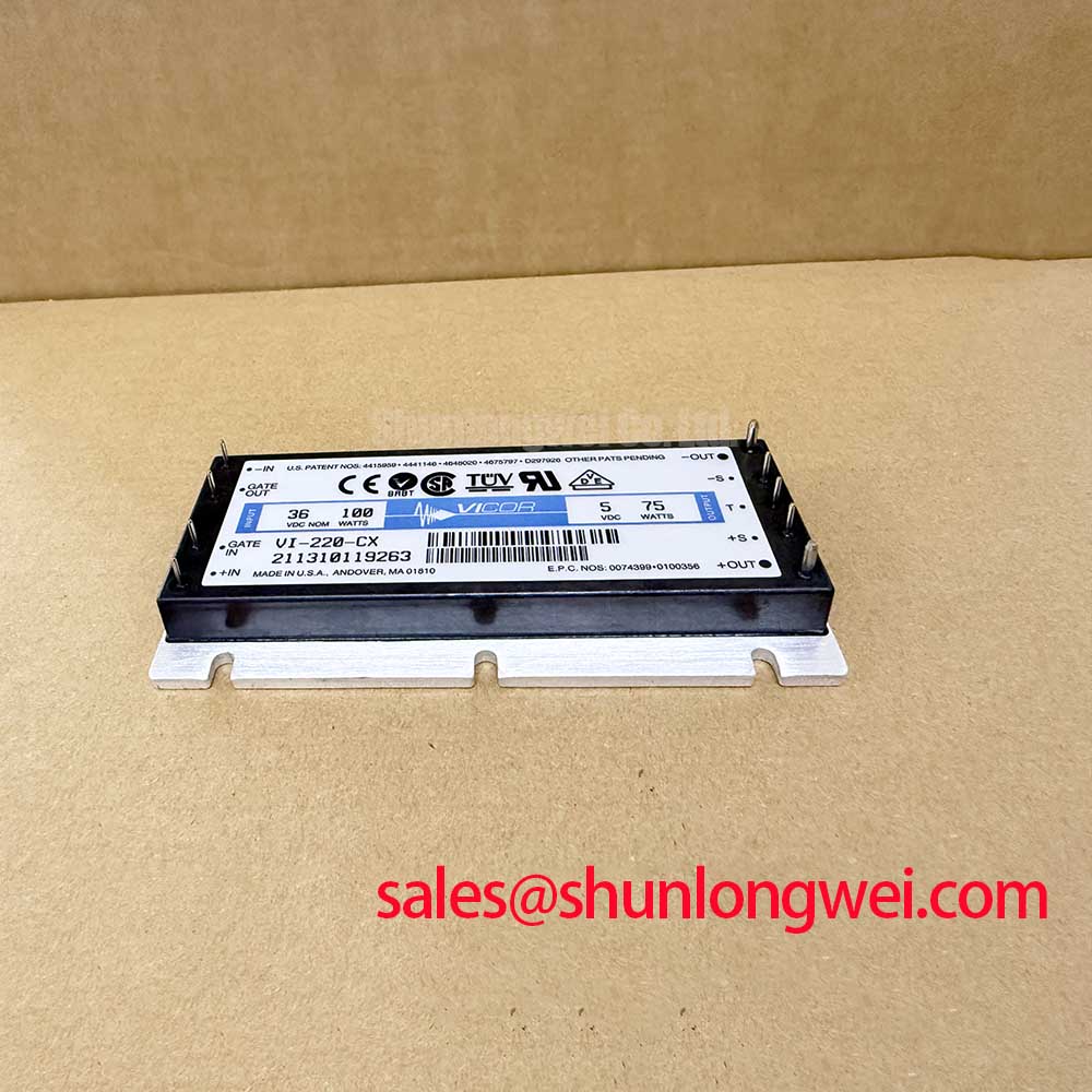
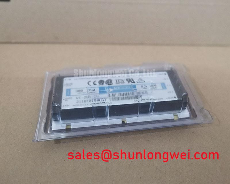
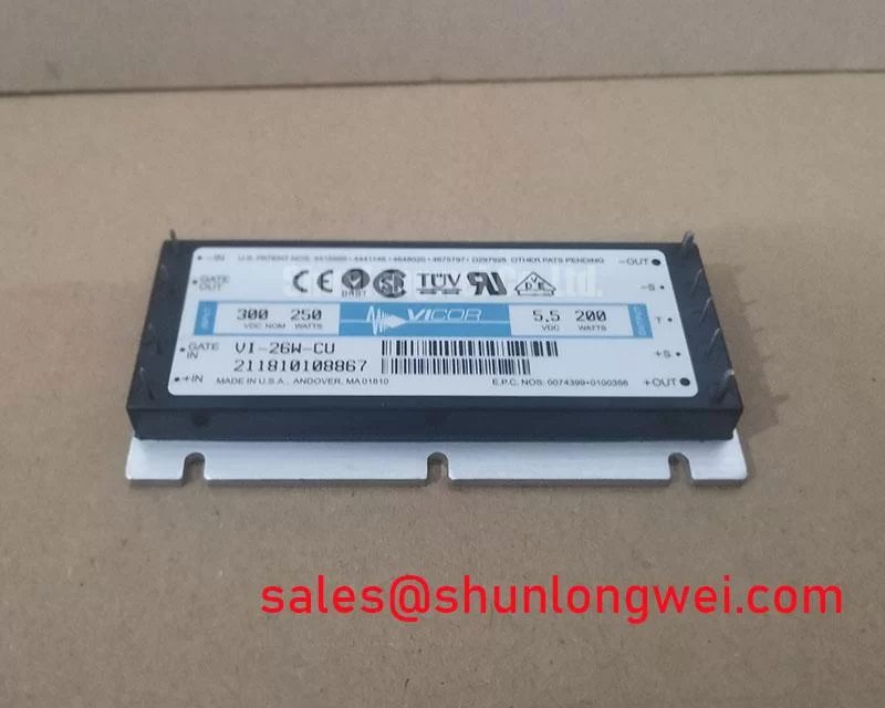
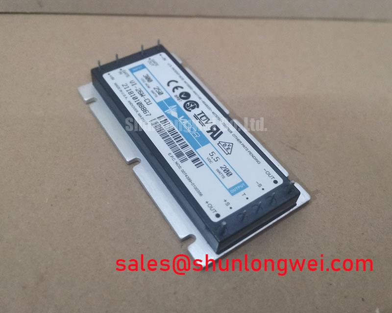
The VI-26W-CU is identified as a Vicor Brick Module power supply and DC DC converter with a Standard Industrial Rating and Standard Operating Current classification. These are official product-record descriptors. The available product information does not establish numerical input voltage, output voltage, output current, isolation rating, switching frequency, pin assignment, or thermal resistance. Those values must be checked against the original Vicor documentation and the host equipment schematic before replacement or new integration.
| Parameter | Recorded Specification | Classification |
|---|---|---|
| Manufacturer | Vicor | Official product identification |
| Part number | VI-26W-CU | Official product identification |
| Product category | Power Supply / DC DC Converter | Official product classification |
| Package style | Brick Module | Official physical specification |
| Voltage classification | Standard Industrial Rating | Official product-record descriptor |
| Current classification | Standard Operating Current | Official product-record descriptor |
For service work, inspect the mounting plane for burrs, contamination, uneven stand offs, and signs that the module has been mechanically stressed by a distorted chassis or cable harness. A brick converter must transfer its internally generated heat through the mounting arrangement specified by the equipment manufacturer. Design Consideration: use a clean, stable contact surface and apply the equipment’s documented mounting method so that thermal contact remains repeatable after service.
The term thermal feedback should be treated carefully in this application. It is not appropriate to assume that the VI-26W-CU provides a particular external thermal feedback terminal or that its thermal behaviour follows the current-sharing characteristics associated with paralleled power switches. When multiple converters or parallel power paths appear in an industrial inverter welder or induction-heating supply, static and dynamic current balance are system-level matters. Engineers should compare module part numbers, output regulation architecture, wiring resistance, remote-sense implementation where present, and control-loop interaction rather than infer balance from the brick outline.
Place the converter so that power conductors and control wiring can be routed separately where the host design permits. Keep return paths intentional and short, particularly where auxiliary power feeds gate-drive boards, current sensors, or controller electronics. If intermittent control resets occur during welding pulses or heating-power transitions, inspect the converter mounting, supply return continuity, connector retention, and local decoupling before attributing the event to the converter itself.
⚠️ Field Alert: Disconnect stored-energy sources and verify the equipment is de-energised before removing converter terminals or connectors.
Transient Dynamics & Electrical Design: Planar Symmetrical Busbar Geometry for VI-26W-CU
A brick DC DC converter should be evaluated within the complete power distribution network, not as an isolated source of switching noise. In inverter welder and medium-frequency induction-heating equipment, large current transitions in the main power stage can couple into auxiliary supplies through shared impedance, magnetic fields, supply rails, and control-ground routing. The VI-26W-CU installation should therefore preserve the original physical wiring path and local capacitors unless the system design has been formally revalidated.
Design Consideration: a planar and closely coupled supply-and-return geometry reduces parasitic loop inductance, which helps suppress overshoot created when current changes rapidly. In engineering terms, a switching transient increases with the product of loop inductance and current-change rate, so a busbar layout, capacitor position, and return path must be assessed together. Peak voltage margins should be verified with correctly referenced switching measurements against the actual DC-link conditions of the equipment.
The converter’s available record does not state a recommended external snubber, gate-drive current, gate resistor, or damping-resistor value. Those are not safe values to prescribe for this model. Where the auxiliary converter powers electronics associated with the primary switching stage, the system engineer should evaluate whether ringing is arriving through the input rail, output rail, control cabling, or measurement setup. Oscilloscope probing should be performed with a suitable low-inductance measurement method and compared with a known-good unit or approved waveform record where available.
Physical symmetry remains useful even when no parallel converter arrangement exists. Pair outgoing and returning conductors, avoid unnecessary cable loops, and prevent high-current busbars from sharing an uncontrolled return section with sensitive controller supplies. These measures are Engineering Recommendations rather than official VI-26W-CU ratings. Their effectiveness depends on the converter’s placement, the enclosure, the primary inverter topology, and the impedance of the connected load.
When reviewing the larger system, a device such as 7MBR30SA-060-50 can be documented as a separate power-stage item in a related topology, but its electrical role, interface, and suitability must be independently checked. It is not a specification substitute for the VI-26W-CU DC DC converter.
Transient Dynamics & Electrical Design: Reinforced Insulation Barrier Integrity for VI-26W-CU
Do not assume a reinforced isolation barrier, a particular dielectric withstand level, or a defined common-mode transient immunity capability for the VI-26W-CU without the applicable Vicor documentation. The present product record identifies a brick module but does not provide an official numerical isolation rating or CMTI value. For equipment repair, verify whether the original circuit requires isolated auxiliary power, the insulation coordination category, the permitted working voltage, and the required creepage and clearance distances at the assembled product level.
Where an industrial power supply contains isolated control domains, inspect the entire barrier path rather than only the converter body. This includes printed-circuit-board spacing, connector shells, cable insulation, contamination, mounting hardware, chassis bonds, and any optically or magnetically coupled interfaces. Moisture, conductive dust, flux residues, and damaged cable sleeving can change the practical insulation performance of an otherwise correctly selected module.
High-voltage power-stage events may also disturb controller references and lead to unwanted switching behaviour in adjacent circuits. The physical mechanism of voltage breakdown is discussed in Avalanche Breakdown in High Voltage Power Semiconductors. This reference describes a semiconductor phenomenon and does not establish an avalanche rating for the VI-26W-CU. Any observed abnormal gate pulse, controller reset, or sensor fault should be investigated using the actual circuit diagram, isolated measurements, and validated timing references.
Some high-voltage assemblies use silicone gel as part of a broader insulation or environmental-protection arrangement. The general material context is described in Silicone Gel Encapsulation for High Voltage Insulation. No claim is made that the VI-26W-CU contains this material or uses any particular encapsulation construction. If the original equipment includes potting or gel around the converter area, restore only the material and process identified by the equipment documentation.
Designers reviewing unwanted turn-on events in an associated IGBT or MOSFET drive stage may consult Evolution of Negative Off-Bias Gate Drive Circuits for circuit-level context. Negative off-bias selection, if used, is a gate-driver system decision and must not be inferred as a requirement or feature of the VI-26W-CU.
VI-26W-CU Circuit Protection & Reliability: Calibrating Transmission Line Impedance Mismatch
Long motor leads, output cables, and high-current interconnects can produce reflected-wave and impedance-mismatch effects in an inverter system. These effects belong to the power-stage and load-cable environment; they should not be assigned to the VI-26W-CU without measured evidence. In a welder or induction-heating installation, a disturbance at the auxiliary converter can result from shared supply impedance, control-cable coupling, inadequate shielding termination, connector movement, or an actual converter fault. Each possibility should be tested separately.
A practical diagnostic sequence begins with visual inspection and continuity checks while the equipment is isolated. Next, compare the converter input condition, output condition, and control behaviour against the original schematic and a known-good channel if one exists. Observe whether the disturbance follows a specific operating transition, cable position, duty profile, cooling condition, or load connection. Avoid treating any single waveform feature as conclusive proof of a failed converter without confirming the measurement reference and probe arrangement.
Where the system design includes output filters, chokes, termination networks, or suppression components, their values and locations must be retained or validated by the responsible system engineer. Engineering Recommendation: minimise uncontrolled cable-loop area and verify voltage peaks under representative switching conditions before changing a filter or rerouting a conductor. The required suppression approach is determined by cable length, inverter topology, load characteristics, switching behaviour, insulation limits, and the documented electrical boundaries of all connected devices.
For sourcing comparison, 7MBR75U2B060-50 is a separately listed power-semiconductor module that may appear in related industrial power equipment documentation. It should be evaluated only against its own manufacturer data, circuit role, mechanical interface, and drive requirements. It is not presented as a direct replacement for the VI-26W-CU.