

Content last revised on October 4, 2026
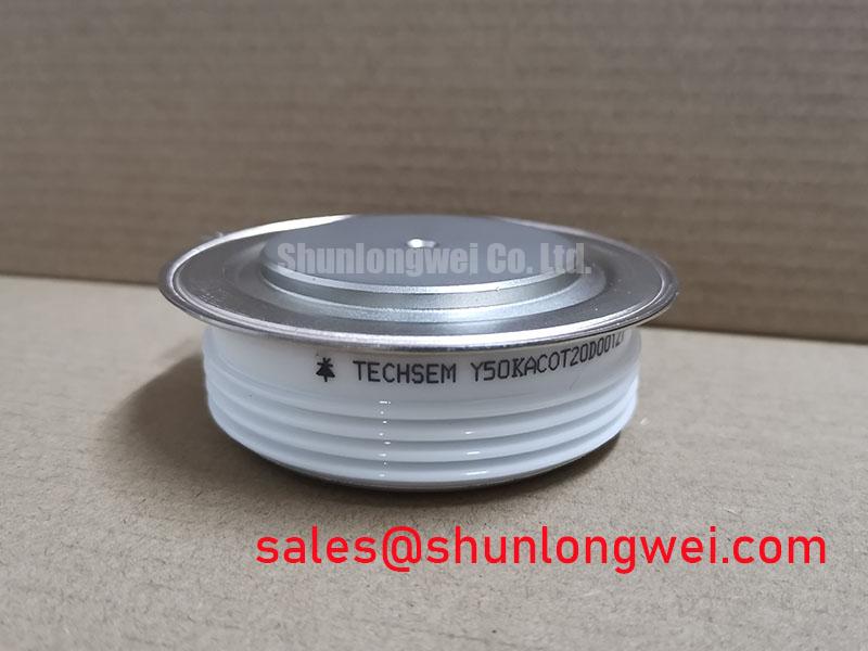
Y50KAC0T20D00127 Operational Boundaries: Evaluating Junction-to-Case Thermal Response
For a machine with repeated acceleration or heavy pulsed loading, a steady heatsink temperature does not describe the highest junction temperature during each pulse. As a Design Consideration, build the thermal assessment from the measured current waveform, applicable conduction and switching losses, and the manufacturer’s junction-to-case transient thermal impedance data. A multi-RC model can represent how temperature responds across different pulse lengths, but its result is only as dependable as the loss inputs and thermal data used. No junction-to-case impedance curve or maximum junction-temperature value is established by the supplied ratings, so a numerical peak-temperature margin cannot responsibly be assigned here.
At commissioning, log case or accessible baseplate temperature alongside load and cooling conditions, then compare repeated runs under equivalent duty. Inspect the heatsink for blocked fins and confirm that the enclosure airflow reaches the mounting surface. If temperature rises while the electrical duty remains comparable, examine airflow and the thermal interface before attributing the change to the semiconductor. Silicone gel is a general high-voltage encapsulation material described in Silicone Gel Encapsulation for High Voltage Insulation; its use inside this specific module is not established by the supplied product information.
For cross-reference work, 6MBP100TEA060-50 can be examined as a separate module listing, not assumed to be an electrical or mechanical replacement. Compare the circuit configuration, terminal map, mounting pattern, cooling interface, and documented ratings before considering either device for the same equipment.
Benchtop Waveform Tuning: Desaturation and Fault Management
Start fault-protection review at the equipment schematic rather than at a proposed trip-time setting. If the documented module topology and installed driver use IGBT desaturation detection, observe collector-emitter voltage and gate-drive behavior during controlled switching tests. A rising collector-emitter voltage under commanded conduction can be a fault indication, but its interpretation depends on the driver’s blanking behavior, switching transients, and the device’s published limits. The supplied product information does not specify a short-circuit withstand time, desaturation threshold, or short-circuit safe operating area for Y50KAC0T20D00127; none should be inferred from its 1200 V and 1270 A ratings.
As a Design Consideration, a staged fault turn-off may reduce inductive overshoot, but the driver response must be checked against the documented device limits and measured DC-link conditions. Record the fault waveform at the module terminals, including peak voltage, rather than relying only on a driver fault flag. The physical reason for examining excessive junction voltage is consistent with impact ionization and avalanche multiplication; that general mechanism does not establish an avalanche rating for this module.
Review a semiconductor fuse separately from electronic fault detection. Its clearing behavior must be coordinated with the available fault current, circuit impedance, and the module’s documented surge or short-circuit limits. Without those device limits and the fuse manufacturer’s clearing data, a claim of protective coordination would be premature.
Field Diagnostics and Commissioning: Baseplate Thermal Interface Control
During installation, clean the mating surfaces and inspect them for debris, damage, and uneven contact before applying thermal interface material. The working aim is a continuous interface without trapped voids or a thick accumulation that impedes heat transfer. A nominal grease thickness, baseplate-curvature allowance, and mounting torque cannot be assigned to Y50KAC0T20D00127 from the supplied specifications. Obtain the applicable mounting drawing and interface-material instructions, then tighten the fasteners progressively in the specified sequence and verify them with a calibrated tool.
Maintenance Note: After isolating the equipment, check fastener condition and airflow whenever a repeatable rise in contact or heatsink temperature appears under comparable load.
When investigating an elevated case temperature, compare temperatures at consistent measurement points and inspect the grease imprint when removal is authorized. An uneven imprint may warrant checking heatsink flatness, fastener loading, and interface coverage; it does not by itself identify a single failed part. In installations exposed to temperature swings, also inspect the enclosure for moisture and condensation before recommissioning. The broader measurement sequence is covered in IGBT Design & Integration, subject to confirming that its IGBT-specific guidance matches the installed topology.
Y50KAC0T20D00127 Thermal-Electrical Optimization: Gate-Loop Geometry
Trace the power-current path and the driver return on the actual module drawing before modifying a gate-drive board. If the documented terminal layout provides a separate auxiliary emitter connection, evaluate whether the driver return can use it without sharing the main load-current path. That separation is a Design Consideration for reducing unwanted gate-voltage disturbance; the presence of such a terminal on Y50KAC0T20D00127 has not been established by the supplied specifications. Keep the verified gate loop compact, then check gate voltage and switching overshoot at the module terminals under representative operating conditions.
If the equipment uses a bootstrap gate supply, inspect its recharge path, capacitor voltage during repeated switching, and diode recovery behavior against the driver documentation. These are system-dependent checks, not factory parameters of this module. Electric material-handling equipment, including forklift traction systems, is a possible compatibility-assessment context only: its DC-link arrangement, switching duty, cooling provision, and physical mounting must each be verified before this module is considered for installation.