


Content last revised on September 18, 2026
Assembly Integrity & Layout Architecture for PM20CEF060-5
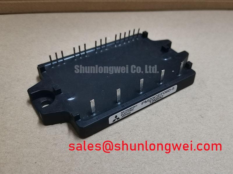
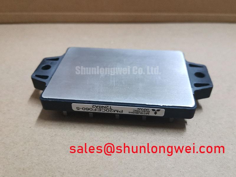
Check the module marking, inspect the housing and terminals, and confirm the inverter nameplate against the 600.0V voltage rating and 20.0A current rating before applying power. The PM20CEF060-5 is a Mitsubishi Electric IPM Module intended for evaluation in industrial power conversion and motor control assemblies, including precision stepper and BLDC servo motion actuators.
The first maintenance task is to establish a known electrical and mechanical baseline. With the equipment isolated, record the terminal identification from the original Mitsubishi Electric documentation and compare it with the board drawing. Do not infer a power, control, or auxiliary terminal from physical position alone. A replacement installation should preserve the original current path, gate drive reference, control isolation, and protective earth arrangement where applicable.
The official product data supplied for this device identifies a 600.0V rated voltage, a 20.0A rated current, and a Mitsubishi IPM Module package. These are product specifications, not a complete system operating envelope. Actual switching stress depends on the DC link, motor cable arrangement, gate driver, switching frequency, load current, cooling path, and protection coordination. Designers should verify all of these conditions against the original equipment documentation before energizing a repaired assembly.
High dv/dt at the switching node can couple through device capacitances and board parasitics into the gate control loop. This may produce an unintended gate-voltage disturbance or cross-conduction event, but the precise mechanism must be confirmed through measurement. The practical layout objective is to keep the gate loop compact, separate high-current commutation paths from control traces, and reference the driver return to the appropriate emitter or control return shown in the applicable pinout. If the equipment uses an auxiliary emitter or a dedicated sense connection, the integrator should verify that the replacement board preserves the intended separation rather than joining terminals casually.
Active Miller clamping and negative gate bias are driver design options, not confirmed internal features or mandatory settings for this particular module. Their suitability depends on the gate driver architecture, isolation method, gate-emitter rating, turn-off behaviour, and the manufacturer’s application data. The system designer should confirm the permitted gate voltage range from the original documentation and validate turn-on and turn-off waveforms with an isolated differential probe.
During fault investigation, compare a suspected unit with a known-good signal path. Check gate-to-emitter behaviour at the driver output, inspect the dead-time relationship, and look for ringing that changes when the probe location changes. A disturbance visible only at a long measurement lead may be a probing artifact. A disturbance that remains at the module terminals should lead to examination of the driver return, copper geometry, connector condition, and switching-node coupling.
For mechanical assembly, clean the heatsink contact surface and check that it is flat, stable, and free from burrs. The appropriate mounting method, thermal interface material, fastener type, and tightening sequence must follow the equipment manufacturer’s instructions. Any suggested torque value must come from the applicable mechanical drawing or module documentation rather than from the current rating alone.
Maintenance Note: Monitor contact temperature during scheduled service and inspect heatsink airflow, dust accumulation, and thermal interface ageing before treating a recurring overtemperature alarm as a semiconductor fault.
Benchtop Waveform Tuning and Isolated Gate Supply Verification
Bench testing should begin with the power stage disabled or operated through an appropriately controlled test arrangement. Confirm the isolation boundary between the control electronics and the power circuit, then verify that the isolated gate supply remains stable during both switching transitions and fault events. Isolation voltage and common-mode transient performance are system-level requirements; the values supplied in the project brief are not official ratings for PM20CEF060-5 and must not be attributed to the module.
The gate supply should be assessed under the actual driver load, including charging and discharging current, bootstrap or isolated-channel behaviour where applicable, and the effect of the driver’s local decoupling. Measure the supply directly at the driver pins while observing the module gate waveform. A supply that appears correct with no switching activity can collapse or oscillate during commutation. Designers should verify the required supply voltage and gate limits from the original Mitsubishi Electric documentation and the equipment schematic.
Busbar geometry deserves the same attention as the gate circuit. Minimize the area enclosed by the DC-link and switching-current loop to reduce parasitic inductance and turn-off overshoot. The required inductance target is determined by the switching current, transition speed, DC-link voltage, module characteristics, and acceptable voltage margin; it should be established through design calculation and oscilloscope testing rather than copied as a universal value. A laminated busbar, short commutation path, and correctly placed film capacitor can reduce the transient seen by the power terminals, but capacitor placement must be checked against the real current loop.
When a turn-off spike appears, inspect the probe connection first, then compare the voltage at the module terminals and at the DC-link capacitor. A difference between these locations can reveal stray inductance in the interconnect. If the spike persists, review the gate resistance, driver return path, freewheel diode recovery behaviour, and snubber position. The reverse-recovery softness factor of a diode is a device and operating-condition characteristic; it should be obtained from the relevant component data rather than assumed from the presence of an IPM.
Long motor cables can behave as transmission-line elements and create reflected-wave stress at the motor or inverter terminals. The risk depends on cable length, impedance, rise time, motor insulation system, grounding, and termination. When evaluating a precision stepper or BLDC servo actuator, inspect the cable routing and shielding arrangement, then verify the motor-terminal waveform with suitable bandwidth and probe technique. Output filtering, damping, or a dv/dt filter may be considered where the system measurements justify it, but the final selection belongs to the equipment designer.
Thermal testing should include the complete transient load profile rather than only a steady-state current reading. The module’s junction temperature response is governed by the thermal interface, heatsink, airflow, duty cycle, switching losses, conduction losses, and transient thermal impedance. A short current pulse cannot be assessed from the 20.0A official rating alone. Use the applicable Mitsubishi Electric thermal curves and the measured case temperature to calculate the system-specific junction-temperature condition.
For related topology review, the CM100DY-12E may be evaluated as a neutral reference for a complementary rectifier-stage discussion. It is not a substitute recommendation for PM20CEF060-5, and voltage, current, pinout, mechanical fit, and control compatibility must be verified independently.
PM20CEF060-5 Operational Boundaries and Environmental Evaluation
The 600.0V and 20.0A values are official product parameters supplied for this page. They should be treated as rating boundaries, not as permission to operate continuously at those values under every thermal or switching condition. The system engineer must establish the usable operating point from the original data sheet, switching waveform, heatsink performance, ambient condition, motor load, and protection response.
Atmospheric neutron effects, cosmic-ray exposure, altitude derating, single-event burnout, and FIT figures require device-specific reliability evidence and an applicable operating profile. No such source is established here, so a numerical failure rate, service-life claim, or altitude derating factor should not be assigned to this module. For equipment installed above its original site elevation, review the manufacturer’s environmental data and the complete inverter design rather than applying a generic semiconductor rule.
A practical environmental inspection is still possible. Record the installation altitude, enclosure temperature, humidity history, condensation exposure, cooling-air condition, and contamination around the heatsink and control board. Look for corrosion at terminals, residue around the module base, discoloured busbar joints, and signs that moisture has entered through cable glands or enclosure seams. These observations do not prove a particular failure mechanism, but they help separate electrical overstress from environmental or assembly-related contributors.
At the bench, use a controlled low-energy inspection before reconnecting the full DC link. Check for unintended conduction paths between the documented terminals, compare resistance trends with an approved reference unit, and examine the gate-control path for damaged driver components. Resistance readings alone cannot certify a power module because internal semiconductor junctions, parallel paths, measurement polarity, and external circuitry affect the result. Any abnormal reading should be followed by isolation of the module from the surrounding circuit.
The manufacturer’s semiconductor resources should be consulted for device-specific application limits and switching guidance. Engineers can review Mitsubishi Electric Power Semiconductors & High-Power Modules and Mitsubishi Electric Global Semiconductor Device Technologies alongside the original equipment documentation.
Where an alternate assembly is being assessed, mechanical dimensions, terminal arrangement, electrical ratings, driver compatibility, thermal impedance, and protection timing must all be checked. The CM300DXDX1-24A can be included in a documented replacement evaluation as a separate device option, but no direct interchangeability should be assumed without schematic and mechanical verification.
Transient Dynamics and Desaturation Detection on PM20CEF060-5
Short-circuit protection should be evaluated as a coordinated system function involving the module, gate driver, current-sensing path, fault logic, isolation barrier, and shutdown sequence. A desaturation detector may be used in some driver architectures, but its threshold, blanking interval, response time, and compatibility with this Mitsubishi Electric IPM must be confirmed from the actual driver documentation. They are not official PM20CEF060-5 parameters supplied here.
During commissioning, verify the protection sequence with a controlled test method approved for the equipment. Observe the gate command, module terminal voltage, current signal, driver fault output, and gate turn-off response on the same time base. The purpose is to establish whether the protection circuit detects the abnormal condition early enough and whether the turn-off event creates an excessive inductive overshoot. Do not infer protection performance from a fault indicator alone.
A two-stage soft turn-off strategy can be considered when the power loop produces significant overshoot during abrupt shutdown. The first stage limits the rate of current change, while the second stage completes gate discharge under the driver’s defined conditions. Whether this approach is suitable depends on the module’s switching behaviour, driver capability, short-circuit withstand data, load inductance, and DC-link voltage. The final timing must be validated by waveform testing against the relevant manufacturer limits.
Check the desaturation or current-sense wiring for excessive loop area, shared return impedance, and coupling from the switching node. A false fault can be associated with blanking, diode recovery, wiring inductance, or an unsuitable sense reference, while a missed fault can result from threshold or timing coordination. These possibilities require measurement rather than a single-cause diagnosis. Compare the fault path with the approved schematic and use a current probe or isolated measurement method suitable for the switching environment.
When a module has experienced a suspected short-circuit event, inspect the gate driver and surrounding passive components before installing another power module. Check the DC-link discharge condition, confirm that the motor cable is disconnected where the service procedure requires it, and verify that the command controller cannot restart the inverter unexpectedly. The Field Engineer’s Handbook provides a useful engineering reference for structured testing, failure analysis, and reliability evaluation.
Record the measured DC-link voltage, current waveform, gate waveform, case temperature, fault response, and test configuration in the maintenance report. This creates a traceable basis for deciding whether the PM20CEF060-5 remains suitable for the original precision motion actuator or whether the wider power stage requires correction before another commissioning attempt.