

Content last revised on October 15, 2026
AA104XD02 Replacement Identification and Verification
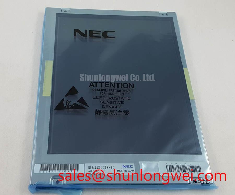
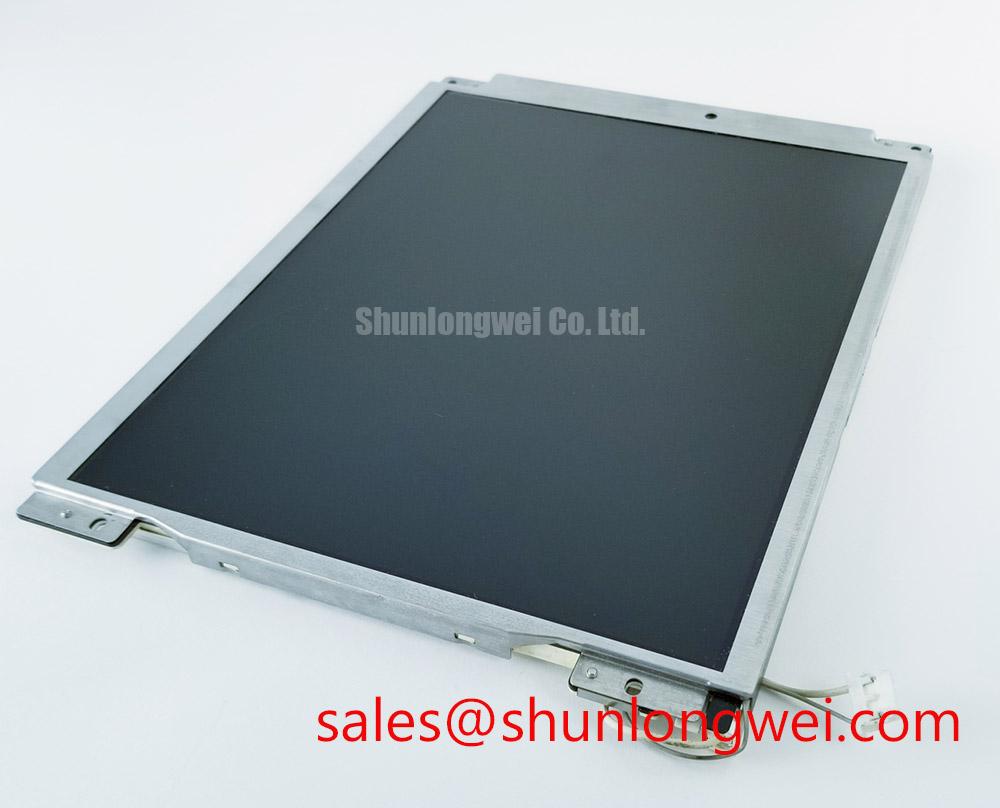
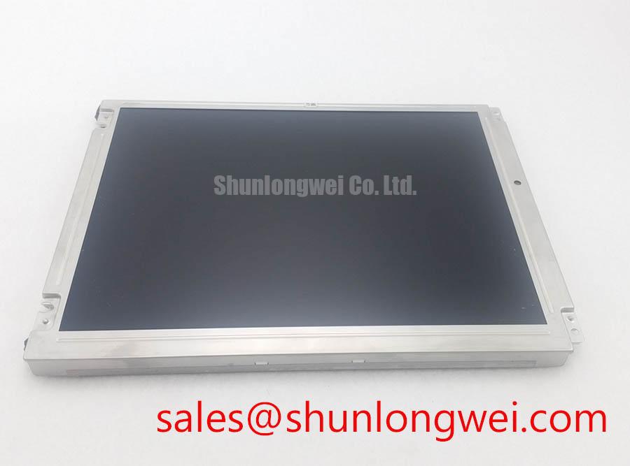
When a precision test instrument shows a dark screen, unstable contrast, or intermittent image loss, isolate the display assembly from its power, signal, and connector path before removing the existing panel. The AA104XD02 is a Mitsubishi Electric Industrial Grade LCD/HMI Panel identified as a TFT LCD active matrix color display module in a decoded baseline standard form factor.
For replacement work, record the original panel label, connector orientation, mounting geometry, host controller interface, and backlight arrangement before installation. The supplied product data does not establish a specific supply voltage, interface protocol, viewing technology, temperature rating, or backlight type for this exact unit, so those items must be matched against the equipment documentation and the removed panel.
| Evaluation Item | AA104XD02 | Reference Display Selection |
|---|---|---|
| Manufacturer | Mitsubishi Electric | Confirm from the original system documentation |
| Product category | Industrial Grade LCD/HMI Panel | Industrial LCD module compatibility required |
| Display construction | TFT LCD Active Matrix Color Display Module | Match optical and electrical architecture |
| Form factor status | Decoded Baseline / Standard Form Factor | Confirm mechanical drawing and connector position |
Super IPS or MVA Wide Symmetric Viewing Cone for Multi Angle Consoles
Do not diagnose a viewing-angle fault from a single operator position. Check the image from the front, upper, lower, left, and right sides while displaying the same grayscale and text screens used by the instrument. TN panels can show grayscale inversion or contrast shifts as the viewing position changes, while IPS and MVA technologies are commonly evaluated where several operators must read the same console. Those optical characteristics are not confirmed as an AA104XD02 specification in the supplied data and should not be treated as a guaranteed feature.
Surface reflection is a separate issue from viewing angle. Under strong factory lighting, move a controlled light source across the bezel and observe whether glare masks characters, waveform traces, or measurement values. Anti-glare treatment, cover glass, and any optical bonding arrangement must be confirmed from the original display documentation rather than inferred from the model number. For a same-class reference during a replacement review, engineers may compare the mechanical and electrical documentation for NL6448BC20-08E, while retaining the AA104XD02 mounting and interface requirements as the governing baseline.
High-speed image links are sensitive to routing, connector seating, and ground reference quality. If the replacement produces color misalignment, split images, or intermittent grayscale artifacts, compare the known-good signal path with an oscilloscope and inspect pair routing, return paths, and connector retention. Differential impedance and skew targets belong to the complete display system design; they are not product specifications established here.
Logic Supply Sequencing and Display Controller Compatibility
Power sequencing should be checked at the panel connector before the display is connected. Capture the host logic rail during startup and shutdown, then compare its order and timing with the original panel documentation. The supplied AA104XD02 data does not confirm whether the required logic supply is 3.3 V or 5.0 V, so the system integrator should verify the required supply voltage from the original panel documentation instead of applying a generic LCD setting.
Incorrect sequencing can appear as a white screen, a blank display, residual image after shutdown, or a controller that fails to recover after repeated power cycling. These symptoms can also involve the host board, cable, backlight circuit, or signal mapping. Check the display enable state, clock activity, data mapping, and reset behavior as one system. JEIDA and VESA mapping are interface properties that require confirmation from the panel and controller documentation before a harness is assembled.
For a related display topology review, the NL8060BC31-32 may be used as a neutral reference point for documentation comparison. It should not be treated as a drop-in replacement without matching connector pinout, timing, mechanical dimensions, optical requirements, and host firmware behavior.
⚠️ Field Alert: Disconnect system power and allow stored energy to discharge before inserting or removing the display cable, because live connector handling can stress signal and supply contacts.
Wide Temperature Evaluation and Sub Zero Liquid Crystal Response
Cold-start testing should begin with the instrument unpowered at the intended environmental condition, followed by observation of image formation, text clarity, contrast, and response during warm-up. Liquid crystal viscosity generally increases at low temperature, which can lengthen visible gray-to-gray transitions and make moving traces appear less distinct. This is a system evaluation point, not a confirmed operating-temperature rating for the AA104XD02.
At elevated temperature, inspect contrast stability, image uniformity, bezel pressure, and cable movement after the enclosure reaches equilibrium. Thermal expansion can alter mechanical stress at the panel frame and connector, while repeated temperature changes can expose weaknesses in mounting alignment or cable strain relief. The enclosure designer should control condensation risk and provide appropriate environmental protection for the complete instrument.
Static measurement screens also deserve an operational review. Long-duration display of fixed menus, grid lines, or status bars can leave temporary image retention on some LCD systems. Use the host application’s screen refresh behavior and display settings as part of the assessment rather than assuming that every panel has identical retention performance. A backlight dimming method, PWM frequency, and duty-cycle behavior must be verified from the actual panel and driver documentation before service modifications are made.
For broader guidance on panel selection, optical behavior, and industrial TFT integration, consult The Ultimate Guide to Industrial TFT LCD Technology. Industrial display references from Tianma NLT Industrial TFT LCD Display Technologies and Winstar Industrial TFT LCD and OLED Display Modules can also help engineers frame optical and environmental verification without assigning unconfirmed characteristics to this Mitsubishi Electric model.
Industrial EMI, Shield Continuity, and Cable Noise Control
When the panel is installed near a variable-frequency drive or other high-noise equipment, inspect the complete cable route rather than the LCD module alone. Pixel jitter, horizontal bands, intermittent color changes, or image dropouts may result from signal integrity, grounding, connector contact, or host electronics. Route display wiring away from switching power paths where the enclosure permits, maintain a controlled return path, and verify shield continuity from the cable termination to the system chassis.
A cable shield should be bonded according to the equipment’s EMC architecture, with attention to enclosure seams, connector shells, and grounding transitions. Common-mode ferrite components can be evaluated when measured interference remains after routing and bonding have been reviewed, but their suitability depends on cable construction, signal bandwidth, and the host interface. They should not be assumed to be part of the AA104XD02 assembly.
For differential links, the system designer should preserve the intended characteristic impedance and minimize pair skew across the cable, connector, and PCB transition. The correct target is determined by the controller and panel interface documentation. Confirm the result with eye-diagram or waveform measurements at the receiver when image errors remain after mechanical and power checks. The AA104XD02 product identity is established here as a Mitsubishi Electric TFT LCD active matrix color display module; final system acceptance depends on verified electrical, optical, mechanical, and environmental compatibility.