Content last revised on October 25, 2026
LB104V03-TJ01 Industrial LCD Panel: First-Line Diagnostic and Integration Guide
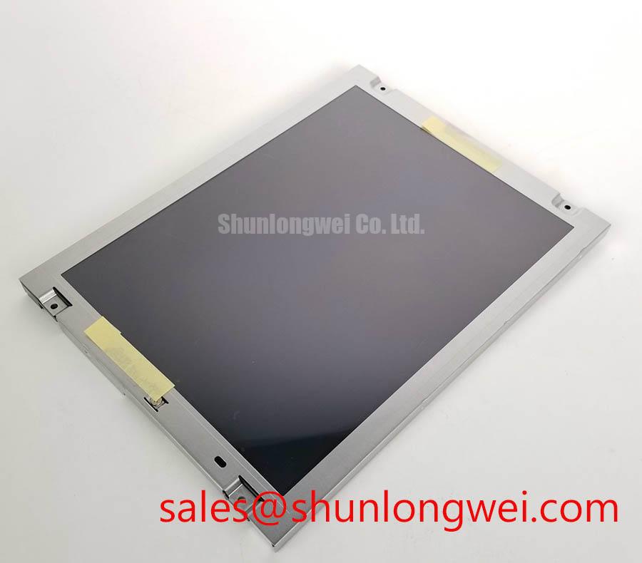
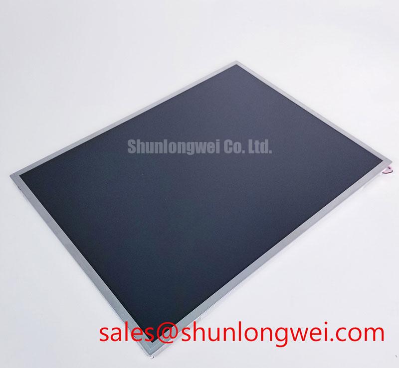
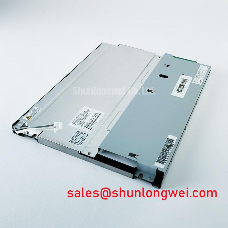
With the machine HMI showing a dark screen, begin by checking the panel under controlled bench lighting, then compare the incoming video signal with a known-good display path before disturbing the flexible cable. The unit under evaluation is the LB104V03-TJ01 from LG Display, classified as an Industrial Grade LCD/HMI Panel in a TFT-LCD active-matrix color display module format. Its recorded specification status is Decoded Baseline / Standard Form Factor.
That identification defines the replacement starting point, but it does not by itself confirm the host controller’s supply voltage, video protocol, connector pin assignment, backlight architecture, or mechanical cutout. The system integrator should verify those items against the original panel documentation and the machine terminal wiring before installation.
Flashlight Dark-Shadow Optical Diagnostic to Isolate Logic vs. Backlight Failure Modes
Use a controlled primary-color test pattern first. Display red, green, and blue fields separately while placing a flashlight at approximately a 45-degree angle across the darkened panel surface. A faint image visible beneath the dark screen can indicate that image data and pixel addressing are active while the illumination path requires investigation; a missing or distorted color field calls for attention to the controller, flexible cable, connector seating, or panel-side driver path.
This optical check helps separate a complete backlight interruption from localized line defects without immediately removing the panel from its frame. A narrow vertical or horizontal defect that remains fixed across all three color fields may require comparison with the known-good signal path and inspection of cable strain near the connector. Avoid flexing the FPC during this test, since movement can temporarily change an intermittent connection and obscure the original fault.
For high-EMI factory equipment, differential routing should be treated as a system-level design consideration. A nominal differential impedance target of 100 Ω ± 10% and a skew budget of 50 ps or less may be used only when they match the host transmitter, receiver, and cable specification. Confirm the actual interface type before applying these values; the LB104V03-TJ01 product identity supplied here does not independently establish a particular LVDS or TTL pinout.
When evaluating a replacement for a machine-tool operator terminal, compare the active image area, connector orientation, mounting points, cable exit direction, and optical stack before powering the display. A mechanically similar panel such as TCG121WXLRFVNN-AN40 should be treated as a separate candidate requiring a full electrical and mechanical compatibility review, not as an automatic substitute.
High-Voltage Striking Potential (1500–1650 Vrms) & Secondary Coil Insulation Testing
Do not assume that a replacement panel uses the same backlight method as the unit removed from the cabinet. The proposed 1500–1650 Vrms striking range, constant-current LED operation, and 1000:1 PWM dimming values belong to application-side evaluation topics unless they are confirmed by the panel and backlight documentation. They must not be treated as official ratings for the LB104V03-TJ01 from the baseline information available here.
If the original assembly contains a high-voltage cold-cathode backlight circuit, insulation testing belongs to the complete lamp, transformer, cable, and enclosure assembly. Isolate the circuit before applying any test instrument, follow the equipment manufacturer’s safety procedure, and prevent the test voltage from reaching the panel signal electronics. Acoustic buzz should be investigated through transformer mounting, drive waveform, mechanical resonance, and enclosure coupling rather than assigned to the LCD module without measurement.
Where a constant-current LED driver is part of the host assembly, verify the driver’s current regulation, enable logic, PWM input range, and thermal behavior against its own documentation. A claimed half-life or MTBF value such as 50,000 hours requires a defined test condition, junction or case temperature, drive current, brightness criterion, and source document. It should not be presented as a guaranteed service-life figure for this display module.
For field work, record whether the image disappears immediately at startup, fades after warming, or remains visible under flashlight illumination. Those observations narrow the test path, but they do not establish a single failed component. Use an oscilloscope and an approved high-voltage probe only where the circuit design and instrument ratings permit it.
High-Humidity Storage Margins (60°C / 90% RH) & Delamination Prevention Protocols
Humidity exposure should be assessed through enclosure condition, condensation history, seal compression, and connector cleanliness rather than by assigning an unverified storage rating to the panel. The proposed 60°C / 90% RH condition is a test scenario, not an official LB104V03-TJ01 environmental specification in the supplied product data.
Before installation, allow a cold display and its host enclosure to reach a stable temperature when condensation is possible. Inspect the perimeter for lifting, clouding, edge discoloration, or contamination, then examine the sealing interface for compression gaps. Mounting pressure should be distributed evenly around the bezel. Localized force can create optical non-uniformity, stress marks, or intermittent connector behavior even when the display initially powers correctly.
At sub-zero temperatures, liquid-crystal viscosity can increase and image response can become slower. This is an engineering consideration for cold-start HMI operation, not a confirmed operating limit for this model. If the machine must start in a cold environment, validate the actual startup sequence with the original controller, observe the image response during warm-up, and ensure that software alarms do not interpret temporary response lag as a communication failure.
PWM backlight control should be evaluated with the driver manufacturer’s limits and the operator’s visual requirements. A working range such as 200 Hz to 1 kHz may be considered during system tuning when supported by the driver, while duty-cycle linearity should be checked with a photometric or camera-based method rather than judged only by eye. Avoid claiming flicker-free performance until the complete display and driver assembly has been tested.
⚠️ Maintenance Note: Inspect the cabinet ventilation path and bezel sealing condition during scheduled service so dust accumulation and gasket compression changes do not create avoidable thermal or condensation stress.
Aluminum Heat Spreader Sizing & Thermal Interface Placement along Narrow Display Edges
Thermal hardware should contact the intended mounting structure without pressing directly on active optical areas, polarizer surfaces, or flexible conductors. An aluminum rail may help distribute heat along a narrow display edge, but its thickness, contact area, interface material, and attachment method must be selected from measured heat generation and enclosure airflow. The LB104V03-TJ01 baseline information does not specify a factory heat-spreader arrangement.
During evaluation, map the bezel and rear-surface temperature after the terminal has reached steady operation. Pay particular attention to local hot spots near the controller board, backlight driver, cable bend, and restricted cabinet corners. Thermal interface material should be applied consistently and kept clear of connectors and inspection openings. Do not use the rail as a structural clamp; the panel should remain supported by a frame that limits vibration while allowing mechanical stress to release evenly.
Long-term static HMI screens also deserve operational attention. Periodic screen changes, controlled brightness, and suitable software display management can reduce the risk of persistent image retention, but the effectiveness depends on the panel construction, drive conditions, temperature, and duty cycle. No L70 or B50 lifetime value should be assigned without a documented test basis.
For TTL or LVDS systems, compare transmitter clock quality, data hold timing, cable routing, and receiver behavior across the actual temperature window. Keep high-current backlight wiring separated from sensitive video pairs where the cabinet layout permits, and verify signal quality at the panel connector rather than only at the controller output. Additional installation and harsh-environment assessment guidance is available through Industrial Display & HMI Solutions. The general operating principles of thin-film-transistor displays are also described in this TFT LCD technology reference.