

Content last revised on September 10, 2026
Suppressing Pixel Jitter & Horizontal White Lines Induced by Adjacent 400V Motor Drives
When an AGV terminal or forklift telematics screen develops moving pixel jitter, intermittent horizontal white lines, or image instability while a nearby motor drive switches, begin with the cable route rather than treating the LCD panel as the confirmed fault. Disconnect power, inspect the display harness for crushed sections and incomplete connector seating, then compare the routing with a known stable installation where available.
Noise entering a display path can originate from motor-drive switching, chassis bonding discontinuities, shared supply return paths, or an interface cable running alongside high-energy conductors. A display that presents a stable image on a bench but becomes unstable in the vehicle or machine enclosure requires system-level verification of its signal path, grounding arrangement, and power source behavior.
⚠️ Field Alert: Disconnect system power and allow stored energy to discharge before unplugging or reseating the display connector, because live connector handling can expose signal contacts to unintended voltage levels.
Design Consideration: A shielded display cable can reduce susceptibility to common-mode interference when its shield termination is planned as part of the whole chassis-grounding strategy. The cable shield must not be treated as a universal correction by itself. Its effectiveness depends on connector construction, enclosure bonding, cable routing, motor-drive emission behavior, and the return-current path established by the equipment design.
For installations using a differential display interface, the system integrator should verify the original interface requirements from the host controller and panel documentation. Values such as differential impedance targets and pair-to-pair timing skew are controlled by the complete signal channel, including the controller board, cable assembly, connectors, and panel input. They are not confirmed official specifications for the LMG7520RPFC from the available factory information.
A practical isolation sequence is to operate the HMI with the traction or motor-drive system inactive, then observe whether the artifact appears only when switching loads are enabled. If a scope measurement is available, compare supply ripple and differential signal quality against a known-good signal path. A change that follows cable position may indicate coupling into the harness; a change that follows a particular controller output may indicate a host-side interface or power-integrity issue. Neither observation alone proves an LCD module defect.
For broader service planning around industrial display cables, grounding, installation environment, and HMI fault isolation, review Industrial Display & HMI Solutions as an engineering reference alongside the original equipment documentation.
Incoming Benchtop Inspection: Display Bonding Integrity
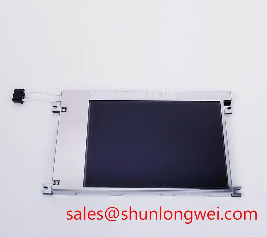
Before fitting the LMG7520RPFC into a field unit, use a controlled bench setup that matches the original host’s verified electrical interface and power sequence. The available official factory information identifies this product as a TFT LCD display module, but does not provide the required input supply, signal standard, connector pin assignment, timing conditions, or backlight electrical data. Those values must be confirmed from the original panel documentation and host equipment records.
A three-stage image check is useful for separating visible display symptoms. First, apply a uniform dark image. Second, apply a uniform bright image. Third, apply saturated red, green, and blue test fields from the verified host signal source. Inspect each image for persistent vertical or horizontal lines, localized discoloration, unstable areas, or sections that change when the enclosure is gently handled. Record observations with the same brightness setting and viewing angle so that comparisons remain meaningful.
A flashlight check can help distinguish an apparent black-screen event from a missing-image event. With the display commanded on, direct light across the front surface from an oblique angle and inspect for a faint image. A faint image can suggest that image data is present while the illumination path needs investigation. An image that remains absent may point toward the host signal, panel power, interface seating, timing sequence, or the panel itself. This is a diagnostic branch, not a single-cause verdict.
The terms COG, TAB, and ACF describe bonding approaches found in many display assemblies, but the available official specifications do not establish the internal construction of this exact model. Avoid pressing on border regions or attempting unapproved rework in an effort to remove a line defect. Any visible line pattern should be documented first and compared before and after cable reseating, host-board substitution, and controlled bench testing.
Direct sunlight readability, anti-glare treatment, contrast ratio, and brightness retention should likewise be verified through the relevant original documentation rather than inferred from the industrial panel category. For AGV and forklift telematics displays, service engineers should assess the installed enclosure, viewing angle, glazing condition, and ambient light exposure as system conditions separate from the identity of the LCD module.
Where a replacement evaluation is required, the TX23D11VM2BAA can be reviewed as another industrial display model. Its mechanical fit, electrical interface, optical characteristics, touch integration, and firmware compatibility must be independently checked; identical application intent does not establish interchangeability.
Chassis Fastener Torque Sizing to Eliminate Optical Mura Defects
Check the panel’s installed perimeter before blaming the image electronics. A display that is visually clean on a bench can show localized brightness variation after installation if the enclosure, gasket, bracket, or fasteners place uneven mechanical load on the module. Inspect for bowed mounting rails, trapped cable material, misaligned standoffs, damaged bezel features, or a support frame that contacts the active viewing area.
Design Consideration: For assemblies that use M3 hardware, cross-pattern tightening and controlled torque can help distribute mounting load more evenly. The correct torque is determined by the original mechanical drawing, screw type, thread engagement, bracket material, gasket stack, and enclosure design. A nominal M3 torque range must never be represented as an official mounting specification for the LMG7520RPFC unless it is confirmed in the relevant KOE or Hitachi documentation.
Optical mura can appear as a cloudy region, a darker patch, or uneven brightness that becomes more visible on a uniform gray or dark image. It may be associated with mounting pressure, but it can also arise from display aging, surface contamination, illumination behavior, temperature, or an upstream image problem. Inspect the module outside the final chassis when permitted by service procedure. If the symptom changes after releasing mechanical load, document the enclosure contact points before considering a panel-level decision.
Cold-start response also requires careful interpretation. Liquid-crystal behavior and the surrounding display assembly can respond differently at low ambient temperature, but the available official information does not state an operating temperature range or a low-temperature response-time value for this model. Do not assume a sub-zero rating, heater requirement, or warm-up profile. The system integrator should verify environmental limits, any heater control logic, and startup sequencing from the original machine documentation.
For a vehicle-mounted HMI, vibration isolation belongs to the equipment-level mechanical design. Engineers should check that the display frame is supported as specified by the enclosure drawing, that no unsupported cable load pulls against the connector, and that vibration countermeasures do not distort the module. A secure connector and strain-relieved harness can be as important to repeatable display behavior as the panel mounting itself.
Suppressing Acoustic Noise & EMI from PWM Brightness Control
When operators report a high-pitched buzz, visible brightness pulsing, or intermittent darkening, inspect the complete illumination and power path: host supply, display cable, controller board, any separate driver assembly, and the panel connection. The official information available for the LMG7520RPFC does not identify whether the module uses a particular backlight technology, whether a separate driver is required, or whether brightness control is supported. Service work must not assume a CCFL or LED configuration.
Acoustic noise can originate from magnetic components, capacitors, mechanical resonance, a switching supply, or a backlight driver located elsewhere in the system. It may become more noticeable at specific dimming settings or under a particular load condition, but the noise source should be isolated by measurement and controlled substitution rather than inferred from the sound alone. Observe whether the sound remains with the display cable disconnected, whether it changes with the host brightness command, and whether the screen image remains stable while the sound is present.
Engineering Recommendation: Where the original system uses PWM brightness control, verify the intended PWM frequency, duty behavior, signal voltage levels, and enable sequencing against the host and panel documentation. Audible-noise avoidance and flicker performance are properties of the complete driver, display, enclosure, and user viewing conditions. They are not established factory ratings for this specific LCD module from the provided verified data.
Do not claim a particular dimming ratio, ignition voltage, illumination life, or service-hour projection for the LMG7520RPFC without the applicable official specification. Backlight open-circuit and short-circuit protection, fault reporting, and overvoltage response may reside in the panel, a dedicated driver, or the host system depending on the equipment architecture. The correct troubleshooting route is to identify the original power topology first, then verify the relevant rails and control signals under normal and fault conditions.
For AGV and forklift telematics displays, evaluate brightness behavior with the actual vehicle supply condition and intended duty cycle. A panel that is stable on a bench supply can behave differently when connected to a vehicle electrical network with changing loads. Confirm supply integrity, connector retention, chassis bonding, and the original sequencing requirements before determining whether the display module is the source of the fault.