


Content last revised on June 1, 2026
Fuji Electric 1MBI6U4-120 IGBT Module: Engineering High-Current Throughput and Thermal Stability
Application Scenarios & Value
Delivering Robust Performance in High-Power Motor Drives and Inverters
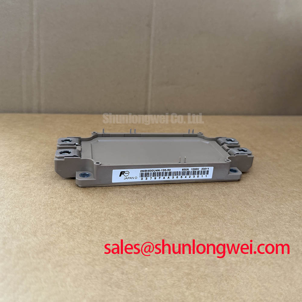
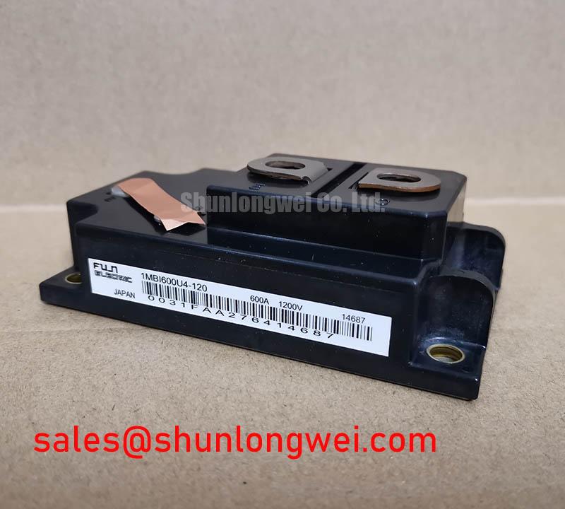
The Fuji Electric 1MBI600U4-120 is an IGBT Module engineered for high-reliability power conversion systems. At its core, this module provides the switching backbone for demanding applications such as large-scale Variable Frequency Drives (VFDs), industrial motor controls, and high-capacity Uninterruptible Power Supply (UPS) systems. The engineering challenge in these environments is managing the immense electrical and thermal stresses generated during high-current switching. The 1MBI600U4-120 directly addresses this with its 600A continuous collector current rating, providing the necessary capacity to drive multi-kilowatt motors without compromising on performance. For systems with slightly lower power demands, the related 6MBI450U-120 offers a similar voltage class with a reduced current rating.
Key Parameter Overview
Decoding the Specs for Efficient Power Switching
The performance of the 1MBI600U4-120 is defined by a set of critical electrical and thermal characteristics. These parameters are fundamental to its integration and operational success in high-power circuits. Understanding these values is the first step in a sound engineering design process.
| Parameter | Symbol | Condition | Value |
|---|---|---|---|
| Collector-Emitter Voltage | VCES | - | 1200V |
| Continuous Collector Current | IC | TC = 80°C | 600A |
| Collector-Emitter Saturation Voltage | VCE(sat) | IC = 600A, VGE = 15V | 2.7V (Typ.) / 3.3V (Max.) |
| Total Power Dissipation | PC | TC = 25°C | 3120W |
| Thermal Resistance (Junction to Case) | Rth(j-c) | IGBT | 0.04 °C/W (Max.) |
| Short Circuit Withstand Time | tsc | VCC = 600V, VGE = 15V | 10µs |
Download the 1MBI600U4-120 datasheet for detailed specifications and performance curves.
Frequently Asked Questions (FAQ)
What is the primary advantage of the low VCE(sat) in the 1MBI600U4-120?
The low collector-emitter saturation voltage (typically 2.7V at 600A) directly translates to lower conduction losses. Think of it as electrical friction; the lower the VCE(sat), the less energy is wasted as heat while the device is switched on. This improves overall system efficiency and reduces the demands on the thermal management system, potentially allowing for a smaller, more cost-effective heatsink.
How does the Rth(j-c) of 0.04 °C/W impact thermal design?
The thermal resistance from junction to case (Rth(j-c)) is a critical measure of how efficiently heat can be extracted from the active silicon die to the module's baseplate. A low value like 0.04 °C/W signifies a highly efficient thermal pathway. For a system designer, this means for every watt of power dissipated, the internal temperature of the IGBT will only rise by 0.04°C above the case temperature. This excellent thermal performance is key to maintaining reliability and preventing premature failure under heavy loads.
Is the 1MBI600U4-120 suitable for high-frequency switching applications?
While this module is optimized for high-current applications, its switching characteristics (turn-on and turn-off times) make it suitable for applications operating in the lower kilohertz range, typical for motor drives and UPS systems. For applications requiring significantly higher switching frequencies, designers must carefully evaluate the trade-off between conduction and switching losses, which increase with frequency.
Technical Deep Dive
A Closer Look at Thermal Resistance and Its Impact on Reliability
The long-term reliability of a high-power module like the 1MBI600U4-120 is fundamentally linked to its Thermal Resistance. The specified maximum Rth(j-c) of 0.04 °C/W is not just a number; it is a promise of thermal stability. This parameter acts as a bottleneck for heat flow. A lower value is analogous to a wider pipe, allowing more heat to escape from the silicon chip to the heatsink with less resistance. In a practical scenario, such as a high-torque motor start-up, the IGBT experiences a surge in current, generating a spike in heat. The module's low thermal resistance ensures this heat is evacuated quickly, preventing the junction temperature from exceeding its maximum rating of 150°C and ensuring the device operates within its Safe Operating Area (SOA). This robust thermal design is a cornerstone of the U-series, enabling sustained performance and longevity in industrial environments.
From a strategic standpoint, investing in a module with superior thermal characteristics enables the development of more power-dense and reliable end-products. It allows engineers to push operational boundaries with greater confidence, knowing a thermal margin is built into the component's core design. This focus on thermal integrity is critical for systems where downtime is not an option, reinforcing the value of datasheet-driven component selection.