

Content last revised on September 27, 2026
Assembly Integrity & Layout Architecture for 250GH-50UL
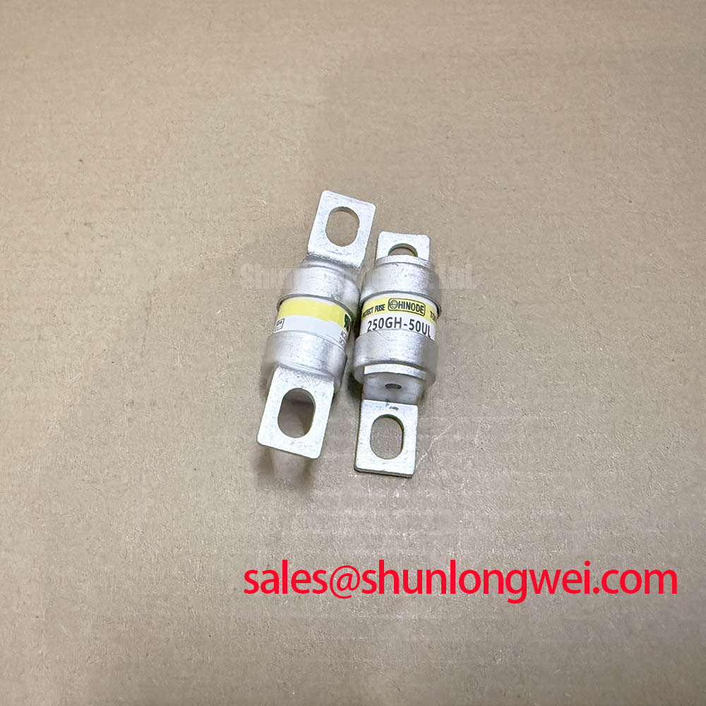
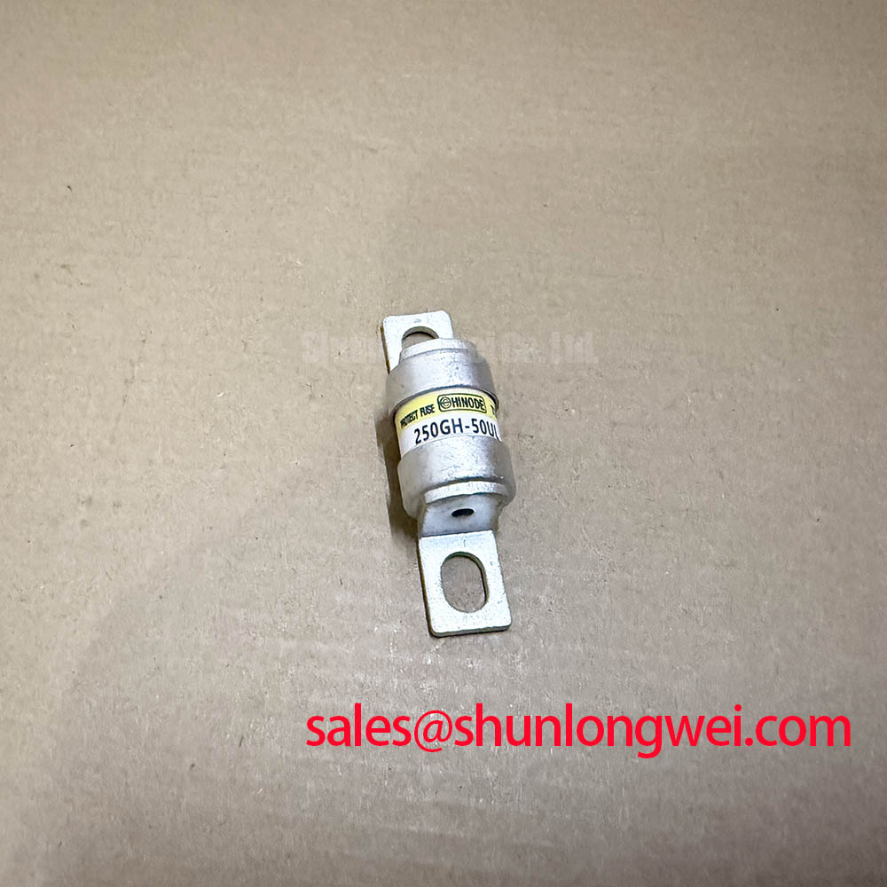
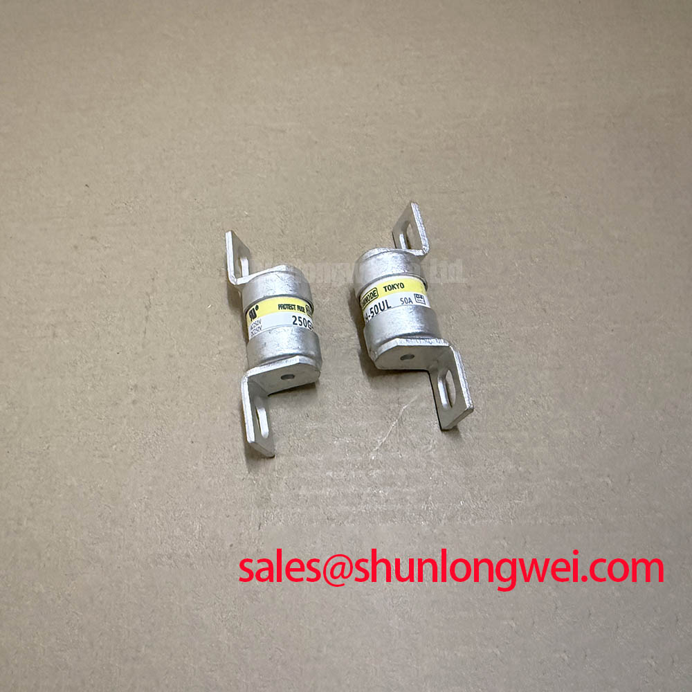
Before installing a 250GH-50UL, isolate the equipment, verify that stored energy has been discharged, and compare the fuse marking, blade geometry, and mounting arrangement with the original assembly. The Hinode 250GH-50UL is a high speed fast-acting fuse, not an IGBT module or gate driver. Its selection therefore depends on circuit voltage, continuous current, prospective fault current, clearing characteristics, and mechanical compatibility rather than gate charge or switching speed.
The specified electrical boundaries are 250 V AC, 50 A, and a 200 kA breaking capacity at 250 V AC. These ratings describe different operating conditions and should not be treated as interchangeable evidence of suitability. The fuse’s ability to interrupt a large prospective fault does not establish that every downstream semiconductor will survive until interruption is complete.
Active Miller clamping belongs to the associated semiconductor gate driver; it is not a function of the 250GH-50UL. For this fuse, assembly integrity begins with the bolted blade connections, the holder or busbar interface, and the space available around the installed device. A mechanically similar fuse can still differ in terminal spacing, contact geometry, and interruption requirements, so physical fit alone is not sufficient for replacement approval.
The following values are the supplied Official Specifications. They establish the product’s stated ratings without adding unsupported mounting dimensions, operating temperatures, approval claims, or installation torque values.
| Parameter | Official Specification |
|---|---|
| Model | 250GH-50UL |
| Manufacturer | Hinode |
| Product category | High speed fast-acting fuse |
| Rated AC voltage | 250 V AC |
| Rated current | 50 A |
| Breaking capacity | 200 kA at 250 V AC |
| Total clearing I²t | 550 A²s at 250 V |
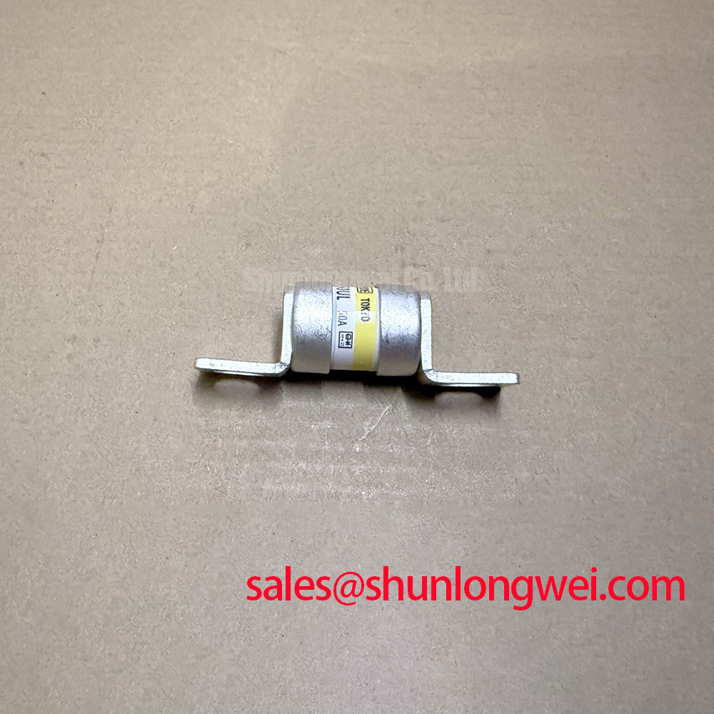
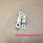
| Body style | Bolted / blade type |
As a Design Consideration, inspect mating contact surfaces, terminal alignment, and the support of adjacent conductors before tightening the assembly. Connections should not force the fuse blades into alignment or use the fuse body to support a displaced busbar. Required fastener torque, mounting orientation, and holder compatibility should come from the applicable product and equipment documentation; the supplied specifications do not establish those details.
For the surrounding power stage, low impedance gate return paths and active Miller clamping can help control unintended semiconductor turn-on when switching transients couple into the gate circuit. Those measures should be evaluated against the actual switch and driver specifications. Neither a particular negative gate bias nor an auxiliary emitter connection can be inferred from this fuse model.
Practical design tip: Where the equipment layout permits, minimize and balance the power stage’s commutation loops to reduce inductive overshoot, then verify semiconductor voltage margins during controlled switching tests.
When documenting the assembly, distinguish the fuse’s connection path from the semiconductor commutation path. A fuse can occupy a supply branch without lying inside every fast switching loop. That distinction helps engineers identify which conductor changes affect protection coordination and which affect switching overshoot.
250GH-50UL Operational Boundaries: Evaluating Overcurrent Protection
Short-circuit safe operating area, or SCSOA, is a semiconductor constraint rather than a fuse rating. The 250GH-50UL does not detect a gate fault, issue a shutdown command, or implement soft turn-off. In an assembly containing controlled power switches, electronic protection and fuse interruption perform separate tasks. Their interaction must be checked against the protected device’s documented fault withstand conditions.
The 200 kA at 250 V AC breaking capacity is an Official Specification for fault interruption under the applicable rating conditions. It is not a continuous current capability, a guaranteed peak let-through current, or a statement that the fuse clears every fault within a fixed interval. Establish the prospective fault current at the installation point and compare it with the fuse rating under the relevant circuit conditions.
The stated 550 A²s total clearing I²t at 250 V is also an Official Specification. As a Design Consideration, total clearing I²t represents the current-squared integral through the complete interruption event, including melting and arcing. It should not be substituted for a pre-arcing value, and it should not be used alone to assign a clearing time to an arbitrary fault waveform.
For semiconductor protection coordination, obtain the fuse’s applicable time-current information and let-through characteristics alongside the protected device’s surge or fault withstand data. Compare values only where waveform, voltage, temperature, and test conditions are compatible. If the device documentation does not provide an applicable withstand limit, the fuse’s I²t rating alone cannot establish protection adequacy.
In an industrial inverter welder or medium-frequency induction heating power supply, first identify the proposed fuse location. An AC supply branch and a DC-link branch impose different interruption conditions. The supplied 250 V AC rating does not establish a DC rating, even where a DC operating voltage appears numerically lower. Any DC application requires an explicitly applicable manufacturer rating and coordination assessment.
For fast fault-current measurements, the Rogowski coil principle provides useful background on current sensing without a magnetic core. As an Engineering Recommendation, verify the measurement system’s bandwidth, integration response, positioning, and acquisition range before interpreting a captured interruption waveform. Sensor behavior and acquisition limitations can otherwise obscure the current peak or clearing interval.
If the protected power stage uses staged shutdown or soft turn-off, validate those functions against its own driver and switch documentation. No semiconductor detection deadline or shutdown sequence should be assigned to the 250GH-50UL from its current rating or total clearing I²t.
Preventing Spurious Faults: Derating and Troubleshooting Guidelines for 250GH-50UL
For the 250GH-50UL, an unexpected fuse opening should prompt an examination of load history, connection condition, and protection coordination rather than an immediate assumption of a defective fuse. As a Design Consideration, repetitive current peaks, local heating, and altered cooling conditions can affect application suitability. The supplied specifications do not include ambient derating curves, cyclic loading limits, or temperature-rise data.
The 50 A rated current is an Official Specification, but it should not be converted into a universal permissible load under every enclosure condition. Designers should verify the manufacturer’s applicable rating conditions and assess the actual current waveform. A current reading taken during steady operation can miss startup stress, intermittent overloads, or changes in the duty cycle.
During troubleshooting, inspect both terminal interfaces and compare their condition with the equipment’s documented assembly requirements. Uneven discoloration or elevated local temperature can justify further investigation, but neither establishes a unique cause. Contact condition, fastener integrity, conductor loading, and nearby heat sources should be checked before attributing an opening event to overcurrent alone.
The positive temperature coefficient of an IGBT’s collector-emitter saturation voltage is not a property that can be assigned to this fuse. Likewise, symmetrical gate wiring concerns dynamic behavior in a semiconductor power stage, not current sharing between replacement fuses. Do not assume that paralleling fuse elements creates an approved higher-current arrangement.
Where a repair also involves the switching assembly, the CM50DY-28H can be reviewed as a separate semiconductor component reference. It is not a same-function substitute for the 250GH-50UL. Fuse selection and semiconductor selection require distinct compatibility checks; a shared nominal current figure would not establish interchangeability or coordinated protection.
For repeatable troubleshooting records, the Field Engineer’s Handbook provides supporting context for testing and failure analysis. Record the fuse location, equipment operating state, measured load behavior, and observations at both connections. Such records support a defensible maintenance decision without turning an isolated event into an unsupported reliability or service-life claim.
Transient Dynamics & Electrical Design for 250GH-50UL
Optocouplers and digital isolation devices belong to the surrounding control system; the 250GH-50UL contains no specified signal isolation interface. Its AC voltage rating and breaking capacity do not establish a reinforced insulation rating, common-mode transient immunity, or gate-trigger immunity. Those characteristics must be verified for the actual driver, isolator, and complete equipment assembly.
As a Design Consideration, assess the installed fuse’s clearances and creepage paths using the applicable equipment requirements. Relevant conditions include working voltage, transient exposure, contamination, enclosure construction, and adjacent conductive hardware. The supplied product data do not support a universal spacing value or a specific dielectric test voltage for this installation.
The distinction between voltage rating and insulation performance matters during maintenance. The principles of dielectric strength and electrical breakdown explain why material and test conditions affect insulation behavior, but they do not establish a product-specific certification. Any insulation test should follow the equipment manufacturer’s procedure, including requirements for disconnecting sensitive electronics.
In a power assembly with suspected transient-related shutdowns, examine the fuse path and the gate-control path separately. Review current measurements for evidence of overload or fault interruption, then assess gate and switching-node waveforms with suitable measurement equipment. A control fault indication does not prove that the fuse operated, and an open fuse does not identify the original switching failure mechanism.
Before approving a replacement installation, resolve the remaining product-specific details: mounting dimensions, holder compatibility, time-current behavior, applicable temperature corrections, and any required approvals. The Hinode 250GH-50UL product page identifies the purchasing reference; installation approval should remain tied to the exact equipment configuration and the applicable manufacturer documentation.