




Content last revised on October 28, 2026
Preventing Spurious Faults: Thermal Interface Material Thickness Uniformity for 2MBI100VA-120
Inspect the thermal compound contact pattern beneath the 2MBI100VA-120 before treating repeated temperature trips as an electrical failure. Uneven transfer onto the heatsink, contamination around mounting holes, or a disturbed interface can help explain why thermal protection operates despite apparently stable load current. Record the operating conditions and compare temperature trends before changing the driver settings.
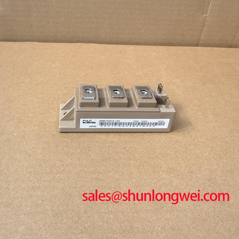
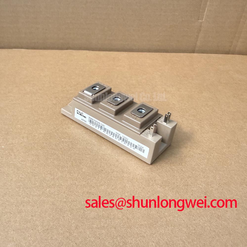
The Fuji Electric 2MBI100VA-120 is an IGBT module with an official rated voltage of 1200 V and an official rated current of 100 A. These ratings establish the starting point for component selection; the installation must also account for the datasheet rating conditions, cooling, switching transients, and protection coordination.
Clean the mating surfaces and inspect their contact pattern before applying fresh thermal interface material. As a Design Consideration, the interface should fill surface irregularities without creating an unnecessarily thick thermal barrier. Select the application method and bond line from the compound supplier’s instructions and the module mounting requirements rather than adopting a universal thickness.
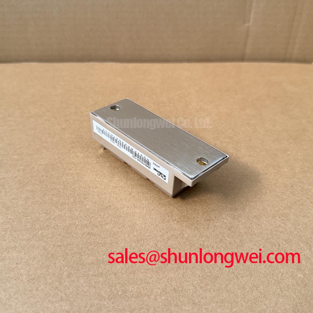
Check heatsink flatness and the module seating surface with appropriate inspection equipment. Baseplate curvature should be assessed against the mechanical drawing, not corrected by forcing the housing flat with mounting screws. A thick deposit of compound is not a dependable remedy for an incompatible mounting surface. Where voids are suspected, examine transfer coverage during a controlled assembly trial and keep the application process consistent between inspections.
As an Engineering Recommendation, seat mounting screws progressively in the specified sequence, then complete tightening with a calibrated tool at the documented torque. Avoid allowing terminal connections to pull the module sideways while its base is being seated. Compare case and heatsink temperature trends under repeatable loading; a changed temperature relationship can justify inspecting contact quality, but does not by itself identify the defective interface.
Keep compound away from electrical terminals and preserve access for inspection. This installation should be treated according to its documented mounting arrangement, not as a press pack assembly requiring improvised spring pressure calibration or an assumed double sided cooling structure.
2MBI100VA-120 Thermal-Electrical Optimization: High di/dt Gate Loop Troubleshooting
Trace the gate driver return to the emitter connection shown on the module terminal diagram before changing gate resistance. As a Design Consideration, shared emitter inductance can produce a voltage disturbance when load current changes rapidly, altering the effective gate to emitter voltage. A separate driver return should use the connection explicitly designated for that purpose; do not infer a Kelvin emitter terminal from connector position or appearance.
Route the gate and its return together, away from the commutating power loop. During testing, observe gate voltage at the relevant module terminals with a suitable differential or isolated measurement arrangement. Probe connections can introduce misleading ringing, so establish measurement integrity before attributing an apparent gate excursion to Miller coupling or driver malfunction. Compare the disturbance with collector voltage transitions and the driver command.
For sourcing decisions, compare the 2MBI100VA-120 with the linked 2MBI300NK-060 as separate engineering candidates, not interchangeable ordering codes. The comparison below separates the supplied specifications from replacement checks requiring the candidate’s datasheet.
| Selection criterion | 2MBI100VA-120 | 2MBI300NK-060 |
|---|---|---|
| Manufacturer | Fuji Electric | Fuji Electric |
| Official rated voltage | 1200 V | Consult datasheet |
| Official rated current | 100 A; apply datasheet rating conditions | Consult datasheet |
| Package and mounting | Consult mechanical drawing | Consult mechanical drawing |
| Replacement qualification | Reference component | Compare circuit configuration, terminals, drive requirements, switching behavior, and mounting |
Protection coordination needs a separate check. As an Engineering Recommendation, evaluate semiconductor fuse clearing characteristics and let through energy against the documented withstand limits of the complete fault path. Fuse I²t alone does not establish IGBT short circuit protection; driver detection and controlled turn off must address the device’s permitted fault interval. Do not treat the rated current as a surge or short circuit withstand specification.
2MBI100VA-120 Thermal-Electrical Optimization: Low-Inductance DC-Bus Integration
Reduce the enclosed area of the commutation loop by arranging the outgoing and return current paths close together. As a Design Consideration, a laminated busbar can reduce parasitic inductance, but the connection geometry between the capacitor, terminals, and switching devices remains important. A compact busbar does not compensate for long terminal extensions.
For an Engineering Calculation, a first order estimate expresses peak collector voltage as DC-link voltage plus stray inductance multiplied by the magnitude of the current fall rate. This relationship explains why faster turn off can increase overshoot; it does not capture every ringing mode or clamping interaction. Evaluate the measured peak against the module’s 1200 V rating across the intended operating conditions, including regeneration.
Pro Tip: Keep commutation paths geometrically balanced, then use double pulse measurements to verify turn off overshoot and gate disturbance before accepting the busbar layout.
Select snubber capacitance and damping from measured ringing, pulse loading, and thermal behavior rather than a fixed capacitance rule. Preserve terminal creepage and clearance when adding conductors or suppression components; the required spacing belongs to the equipment insulation design and applicable installation requirements.
When evaluating compatibility with commercial string inverters or micro-grid energy storage converters, engineers can use Peak Efficiency in Solar and Energy Storage as additional topology context, while retaining the actual circuit schematic and switching measurements as acceptance evidence. Where a system includes regenerative braking, its chopper and resistor require independent energy and duty assessment. The Fuji Electric Brake Chopper IGBT Modules page provides product category context, not confirmation that this module is a dedicated brake chopper.
Transient Dynamics and Electrical Design: Driver Power Stage Start-Up for 2MBI100VA-120
Verify that the gate driver reaches a defined off state before enabling the DC-link contactor or precharge sequence. As an Engineering Recommendation, the control logic should prevent switching while the auxiliary supply is unstable, and the undervoltage lockout response should maintain a controlled gate state during both startup and supply collapse.
If the qualified driver uses negative turn off bias, assess that bias against the module’s permitted gate voltage and the driver’s operating limits. Negative bias is not a substitute for a short return path or adequate Miller current handling. Observe the gate during auxiliary supply ramping, controller reset, and DC-link charging rather than checking only steady state operation.
Separate DC-link capacitor charging from gate driver readiness during troubleshooting. Precharge limits charging current, while driver interlocks prevent unintended switching; one function does not prove the other is working. Compare the enable signals, auxiliary rails, and gate waveform on the same time reference to locate sequencing errors without assuming a single cause for a startup trip.
The Fuji Electric IGBT module portfolio, including seventh-generation X-Series products, offers manufacturer context for driver and technology comparisons; those newer product characteristics should not be assigned to the 2MBI100VA-120. Complete commissioning by testing loss of auxiliary power and restoration of control power, confirming that switching remains inhibited until the intended readiness conditions return.