



Content last revised on October 29, 2026
Benchtop Waveform Tuning: Mitigating Stress via Output Sinusoidal Filter vs dv/dt Reactor on 2MBI300UD-120-02
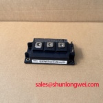
| Model | 2MBI300UD-120-02 |
|---|---|
| Manufacturer | Fuji Electric |
| Category | IGBT Module |
| Topology | 2-in-1 Half-Bridge IGBT |
| Series | 5th Gen U-Series |
| Rated voltage | 1200 V |
| Rated current | 300 A |
| Package | Fuji Power Module |
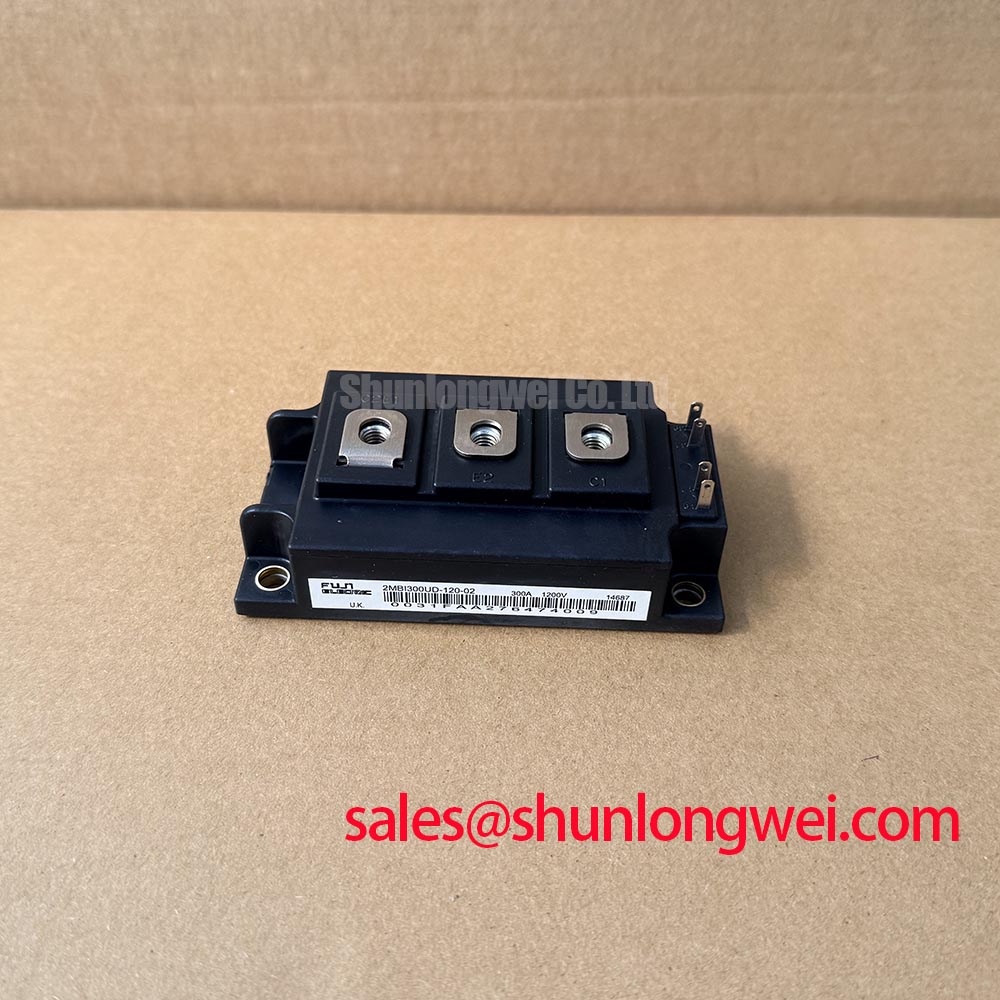
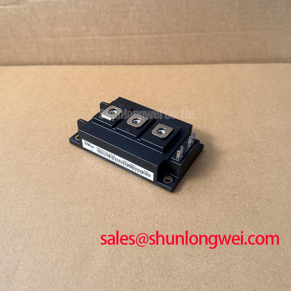
With the inverter isolated and its DC link discharged, inspect the module terminals and record a baseline waveform before changing an output filter or reactor. The 2MBI300UD-120-02 is specified as a 1200 V, 300 A, 2-in-1 half-bridge IGBT module in Fuji Electric’s 5th Gen U-Series. Those are module ratings, not a complete system operating point; actual switching stress depends on the DC link, load, switching conditions, wiring, and cooling.
For an inverter welder or medium-frequency induction-heating supply under evaluation, compare voltage at the inverter output and at the load using suitably rated probes and a repeatable operating condition. Long motor leads can interact with the system’s impedance and contribute to terminal reflections, but the magnitude is installation-dependent. Do not assume a particular spike level or prescribe a filter from cable length alone. A dv/dt reactor and a sinusoidal output filter have different effects on the waveform and system response; designers should assess load requirements, switching behavior, filter losses, and control-loop compatibility before selecting either approach.
Design Consideration: Keep commutation paths compact and preserve appropriate electrical clearance for the actual working voltage and installation environment. If measured overshoot changes with cable routing or load, compare those waveforms with the original system baseline and verify peak voltage margins during switching tests. The 1MBI300S-120 is another module listing that can be reviewed for a documented, application-specific comparison; its presence does not establish drop-in compatibility.
Preventing Spurious Faults: Desaturation Detection Guidelines for 2MBI300UD-120-02
When a desaturation or overcurrent trip appears, capture the gate-emitter and collector-emitter waveforms at the module, then correlate them with the driver fault output and DC-link behavior. The supplied product data establishes the half-bridge topology and voltage and current ratings, but does not state a short-circuit withstand time, desaturation threshold, or soft-turn-off profile. Do not treat a sub-10-microsecond detection target or a particular short-circuit sequence as a guaranteed capability of this part.
Engineering Recommendation: Set detection and shutdown behavior from the verified device documentation, gate-driver characteristics, and measured switching response. A two-stage turn-off can be evaluated as a system-level method for controlling inductive overshoot, but its timing and gate behavior must be validated against the driver, layout, and fault conditions. Record the event with adequate bandwidth, check for noise coupling into the sense path, and distinguish a genuine fault from a transient or measurement artifact before changing protection thresholds.
Coordinate any semiconductor fuse with the module’s documented surge and protection limits and the complete circuit’s prospective fault current. Fuse clearing behavior and device withstand cannot be inferred from the 300 A nominal current rating alone. Fuji Electric’s RC-IGBT Modules and 7th-Gen X-Series IGBT Modules provide manufacturer product-family context; neither reference changes this model’s stated ratings.
2MBI300UD-120-02 Thermal-Electrical Optimization: Static and Dynamic Current Distribution
For parallel-device investigations, measure each branch current and temperature under the same stabilized operating condition, then compare gate signals at the module terminals. The 300 A rating applies to the specified module, not automatically to a parallel assembly or a particular thermal environment. The available product parameters do not provide VCE(sat) temperature curves or dynamic sharing limits, so do not assume a specific positive temperature coefficient or derive a safe current-sharing allowance from the nominal rating.
Design Consideration: Use symmetrical power and gate-loop routing where parallel operation is part of the system design, and verify current balance during switching as well as steady conduction. Differences in parasitic impedance, driver timing, thermal paths, and connection resistance may affect sharing. Check the physical joints and compare branch waveforms before attributing an imbalance to the module. Thermal measurements should reflect the installed cooling interface and operating cycle, not an isolated bench reading.
Regenerative braking and braking-resistor energy handling are system functions. If the module is used in a topology that includes a braking chopper or bidirectional DC-DC stage, verify switching losses, transient current, thermal cycling, and protection coordination against the complete circuit and the applicable Fuji documentation. No lifetime extension or surge capability follows solely from the series name or current rating. For broader IGBT technology context, see Unlocking Efficiency in Industrial Drives; it is background material, not a substitute for this module’s ratings.
Benchtop Waveform Tuning: Mitigating Stress via Thermal Paste Degradation Prevention and Mounting
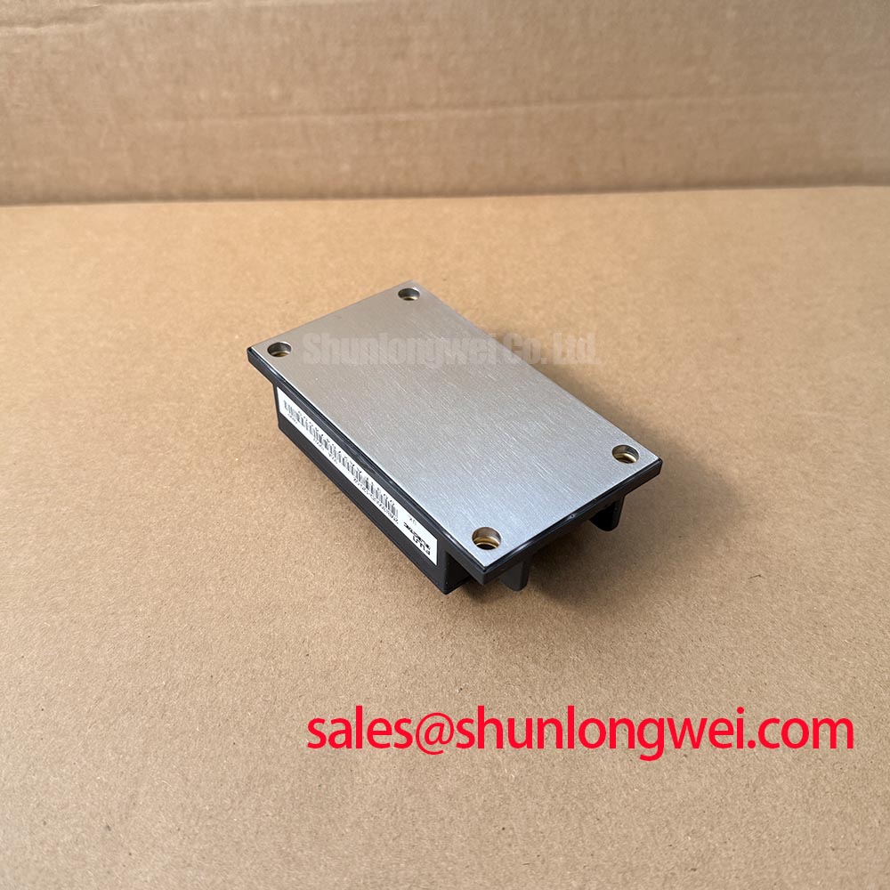
Before mounting, clean the heat-sink contact area and module base, inspect both surfaces for debris or visible damage, and confirm that the mechanical stack matches the equipment drawing. The specified package is Fuji Power Module; no module dimensions, baseplate flatness tolerance, thermal-interface material thickness, or mounting torque are provided in the product parameters above. Use the applicable manufacturer mechanical documentation for those values rather than adopting a generic thickness or torque as an official specification.
Apply the thermal interface material using the material supplier’s process and the assembly’s validated method, aiming for consistent contact without contamination. Tighten fasteners in the prescribed sequence and stages when that procedure is defined for the assembly. Do not compensate for suspected baseplate curvature by arbitrarily increasing torque; inspect the mating surfaces and verify contact using the equipment’s approved assembly checks. After installation, review thermal behavior under a controlled load and compare it with the system’s known-good baseline.
💡 Bench Tip: Use ESD precautions during handling and compare cold, unpowered terminal checks with a known-good reference of the same configuration; a multimeter diode-mode reading alone does not establish module health or replace the specified test procedure.