




Content last revised on October 27, 2026
6MBI150UB-120-52 Identification and Inspection
- Isolate the supply, verify DC-link discharge, and disconnect parallel current paths before comparing cold-state resistance across the power terminals.
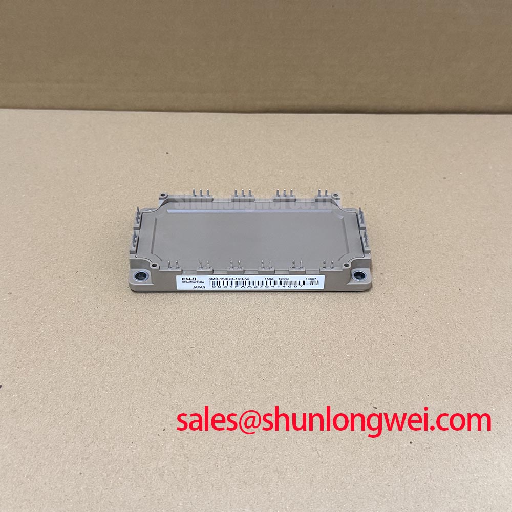
- Check the 6MBI150UB-120-52 marking against the equipment parts record and inspect terminal positions before removing the existing wiring.
- Inspect the mounting surface, terminal joints, and heatsink contact area for distortion, contamination, or signs of localized overheating.
- Check the gate-driver supply and fault-interlock wiring before reconnecting the power stage.
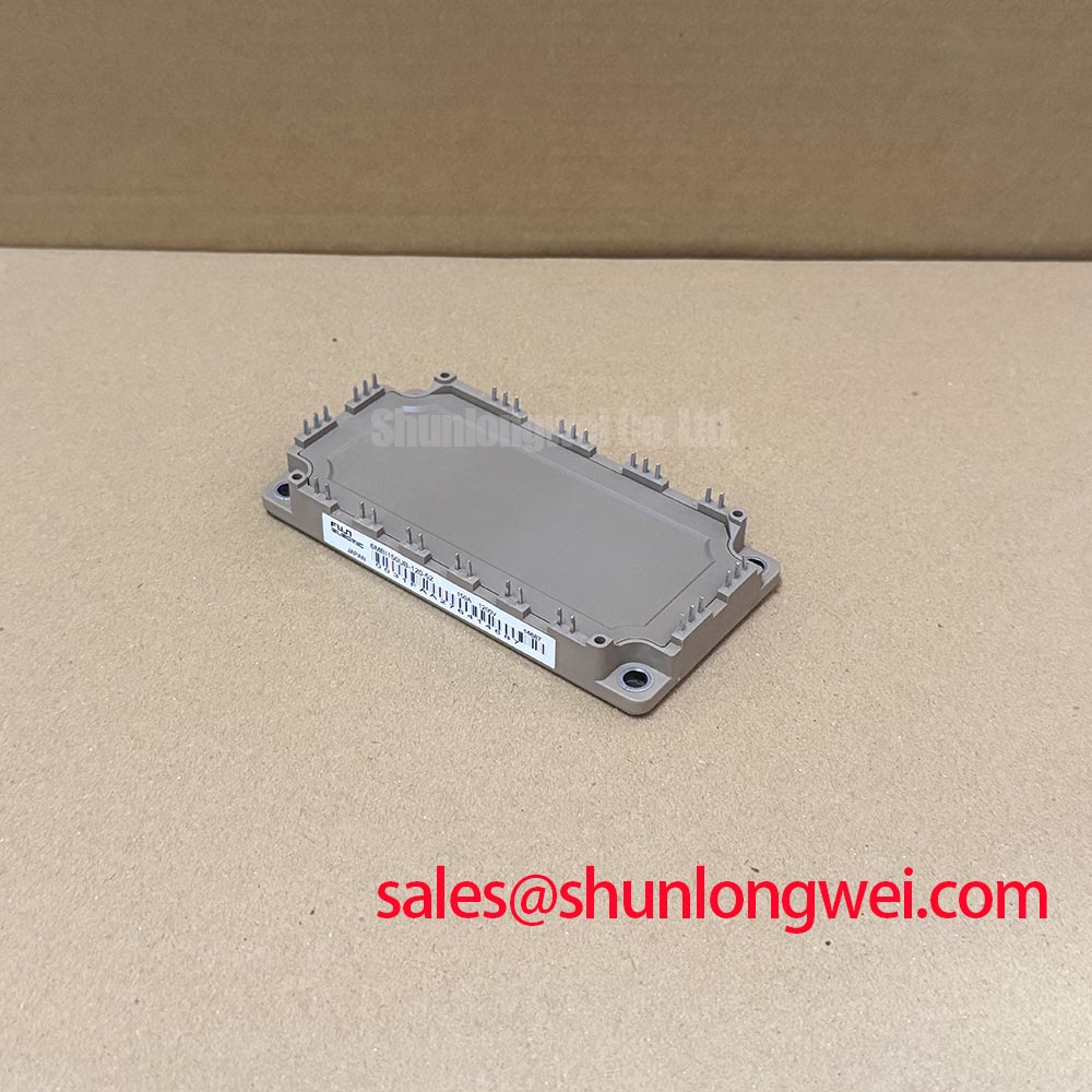
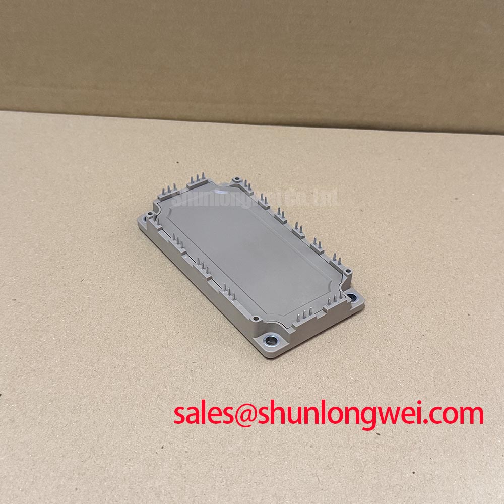
The Fuji Electric 6MBI150UB-120-52 is a 1200 V, 150 A IGBT module in a Fuji Power Module package. For a stopped machine, these identity checks establish the starting point; restoring operation also requires matching the electrical connections, protection behavior, and cooling arrangement.
| Product attribute | Specification | Parameter identity |
|---|---|---|
| Manufacturer | Fuji Electric | Product identification |
| Model | 6MBI150UB-120-52 | Product identification |
| Rated voltage | 1200 V | Official Specification |
| Rated current | 150 A | Official Specification; operating conditions require datasheet review |
| Package designation | Fuji Power Module | Specified package |
| Detailed integration limits | Consult Datasheet | Terminal drawing, gate limits, switching conditions, thermal characteristics, and mounting requirements |
For compatibility assessment in a heavy-duty variable-frequency AC motor drive, compare the complete equipment bill of materials rather than selecting by voltage and current alone. The 2MBI150U4B-120 belongs in a separate topology and interface comparison, not a verified direct-replacement claim. Terminal functions, circuit configuration, mounting geometry, and driver compatibility must agree before any substitution is accepted.
6MBI150UB-120-52 Circuit Protection & Reliability: Calibrating Short-Circuit Energy Let-Through Matching
Compare the installed semiconductor fuse’s total clearing I²t at the actual circuit voltage with the protection requirements of the complete power stage. Design Consideration: fuse coordination addresses fault interruption, while fast gate-driver protection addresses semiconductor fault stress; neither function substitutes for the other.
A fuse’s total clearing I²t describes its current-squared time integral through interruption. An IGBT short-circuit withstand specification describes behavior under defined gate drive, voltage, and temperature conditions. These are not interchangeable ratings, so a fuse comparison alone cannot establish that the module will survive a short circuit or that its case will remain intact. Check fuse interrupting capability, circuit fault current, driver fault-detection delay, and controlled shutdown together.
After a protective trip, record which protection operated before replacing the fuse. With the circuit isolated, inspect the DC-link connections and compare power-terminal measurements across equivalent paths. An unusual reading can identify a path requiring further isolation, but connected capacitors, diodes, and parallel circuitry can influence the result. Preserve fault logs so an overload event is not mistaken for a hard short.
Design Consideration: keep the commutation loop compact to reduce inductive turn-off overshoot, while preserving the equipment’s required electrical clearances. Examine busbar joint alignment and snubber connections after maintenance. The guidance in Mastering Power System Dynamics provides context for investigating parasitic inductance and damping; component values must follow measured switching behavior.
Trace any braking and auxiliary branches separately from the inverter output. Check the braking controller, resistor circuit, and associated protective devices when trips coincide with deceleration. If the equipment records identify a 6MBI300U-170 elsewhere in the assembly, establish its actual circuit role from the schematic rather than treating it as a front-end rectifier or an interchangeable protection component.
Preventing Spurious Faults: Gate Driver Auxiliary Power Sequencing Guidelines for 6MBI150UB-120-52
Verify that the driver supplies reach their valid operating state and that the fault interlocks hold switching disabled before the equipment enables the high-voltage power stage. Design Consideration: startup and shutdown sequencing should maintain a controlled gate state through auxiliary-supply ramping, undervoltage, and loss of controller commands.
Capture the driver supply, enable signal, fault output, and gate-to-emitter waveform during startup and shutdown using appropriately rated measurement equipment. Check whether an undervoltage event reliably inhibits the affected switches. A gate waveform observed during normal running does not establish what happens while an isolated supply is collapsing or restarting.
Negative gate bias is a system-level design choice, not a voltage prescription established by the module’s headline ratings. Where the existing driver uses it, verify its behavior against the module’s gate limits and the driver’s permitted operating range. Evaluate gate voltage at the module connection, because shared return-path impedance can make a driver-board measurement look quieter than the actual gate-to-emitter waveform.
Engineering Recommendation: assess driver sourcing and sinking capability together with gate charge, switching frequency, and the intended transition behavior. Select external gate resistance by balancing switching loss against ringing and unintended turn-on, then validate under representative load conditions. Separate turn-on and turn-off paths require assessment of both transitions rather than assuming a single resistance controls every switching event.
Use the Fuji Electric V-Series IGBT Application Manual for general gate-drive and protection principles, not as the specification for this UB-series model. Fuji Electric’s PIM 7-Pack documentation also concerns a distinct module category; its integrated functions must not be assumed for this part.
Preventing Spurious Faults: Junction-to-Case Thermal Network Simulation Guidelines for 6MBI150UB-120-52
Reconstruct the overload’s current, switching activity, duration, and repetition before evaluating the module’s junction-temperature excursion. Design Consideration: a heatsink temperature reading cannot resolve the faster internal temperature rise associated with a short load pulse.
A transient thermal assessment should combine condition-dependent semiconductor losses with the applicable junction-to-case thermal impedance. If a multi-RC model is used, derive its coefficients from the relevant manufacturer thermal data and check that its response reproduces the published curve. Conduction and switching losses should reflect the actual operating waveform, including diode conduction and recovery where applicable.
For repeated overloads, carry the thermal state forward between pulses instead of restarting every event at the measured case temperature. Compare the predicted peak junction temperature against the applicable limit using the measured case boundary condition. This is an Engineering Calculation workflow, not a model-specific temperature or overload guarantee.
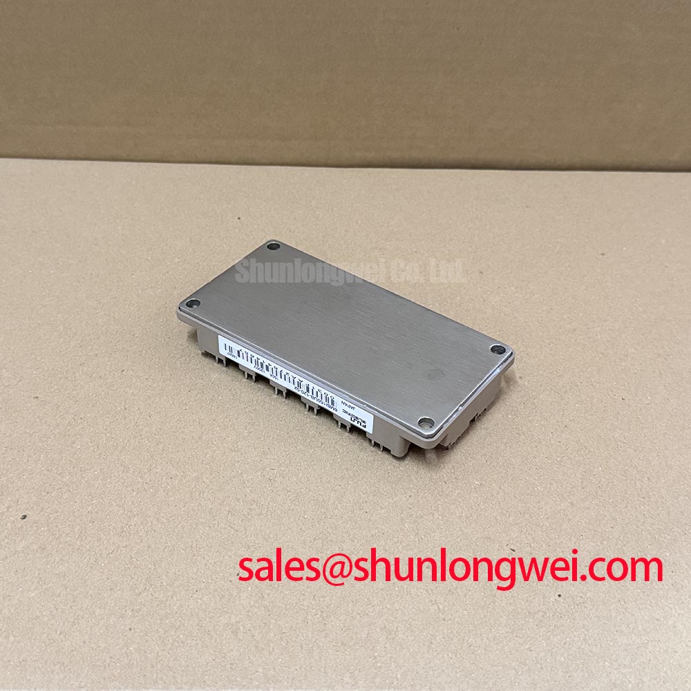
Inspect the mechanical heat path before changing the cooling system. Check mating-surface condition, mounting sequence, heatsink flatness, and the specified thermal-interface application. Field Alert: Follow the applicable mounting torque and tightening sequence, and apply the specified thermal interface evenly rather than compensating for poor contact by tightening harder.
After reassembly, compare temperature trends at repeatable load points and correlate them with electrical loss measurements. A localized temperature difference can justify checking contact quality or current distribution, but it does not establish a single failure cause. Resolve inconsistent measurements before using the thermal model to approve repeated overload operation.