

Content last revised on October 25, 2026
6MBP100RTB060 Circuit Protection & Reliability: Calibrating Optocoupler vs Digital Coreless Transformer
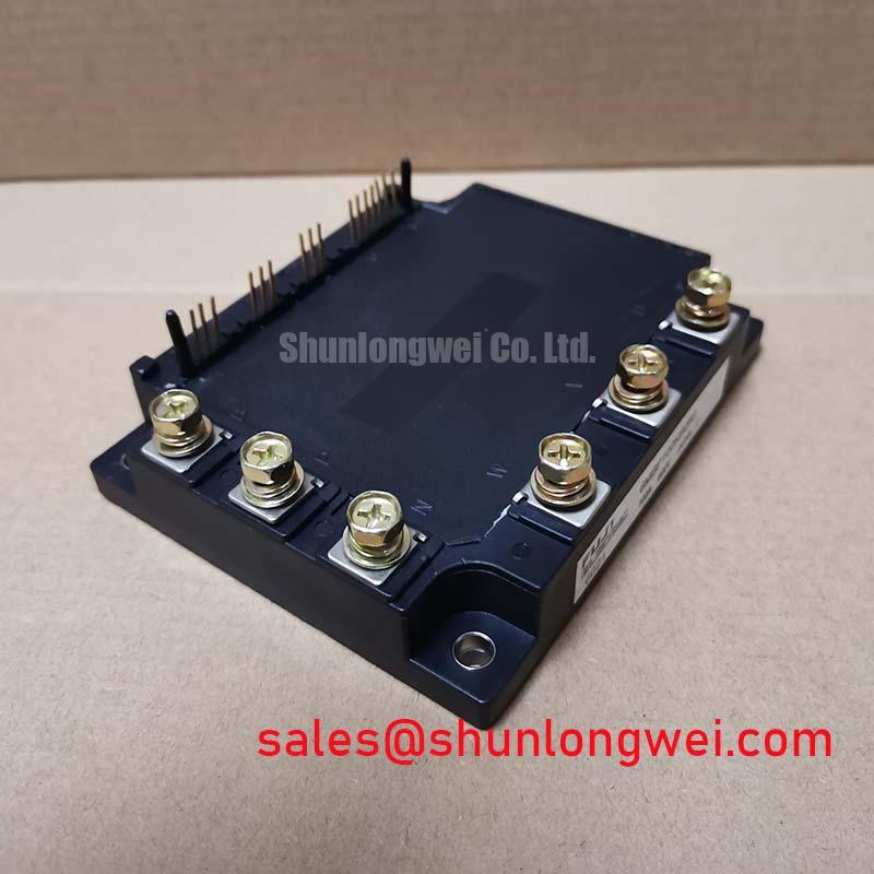
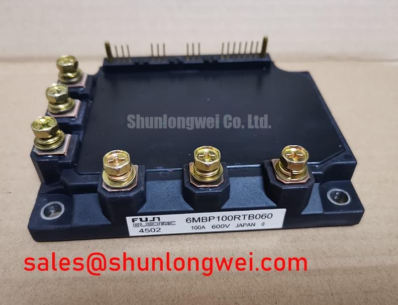
The 6MBP100RTB060 is identified by the supplied factory data as a Fuji Electric power module rated at 600.0 V and 100.0 A, housed in a Fuji Power Module package. These are the product-level ratings to record during incoming inspection. They do not, by themselves, confirm the performance of an external optocoupler, digital isolator, gate driver, or protection circuit installed around the module.
In a replacement evaluation, inspect the isolation path as a complete system. An optocoupler interface and a digital coreless transformer interface can respond differently to common-mode voltage movement, propagation delay, supply variation, and layout parasitics. The practical objective is to prevent a false gate pulse while the power bridge is experiencing high dv/dt. Designers evaluating reinforced isolation should verify the required working voltage, impulse withstand level, creepage, clearance, and common-mode transient immunity from the selected driver documentation. A target such as reinforced isolation above 5 kV or CMTI above 100 kV/µs is a Design Consideration, not an official rating assigned here to the Fuji module.
Route the isolated control return and the high-current commutation loop according to the driver manufacturer’s layout guidance. Keep the gate-drive reference away from switching-node copper, avoid routing logic traces alongside the collector or emitter power path, and check that the isolation barrier is not narrowed by mounting hardware, contamination, or cable shields. Where the original assembly used an optocoupler, replacing only the signal isolator with a digital device can alter pulse width and fault timing. The engineer should compare the output waveform at the driver pins and at the module gate terminals rather than assuming functional interchangeability.
During troubleshooting, monitor the gate command, gate-emitter voltage, collector-emitter voltage, and fault feedback on the same time base. A pulse visible at the controller but absent at the driver output points toward the interface, supply, or enable chain. A clean driver output with abnormal switching at the power terminals calls for inspection of gate-loop inductance, emitter reference integrity, and power commutation geometry. This approach avoids attributing every intermittent trip directly to the module.
The Fuji Electric Power Semiconductor and IPM Modules resource provides useful manufacturer-level context for module families and application terminology. For a repair assembly with a related topology, engineers may also review the neutral product reference for 6MBP150RTC060A when checking how an associated rectifier or front-end stage is identified in the system bill of materials.
Preventing Spurious Faults: Transmission Line Impedance Mismatch: Design Guidelines for 6MBP100RTB060
Long motor leads and poorly controlled switching paths can reflect fast voltage transitions back toward the inverter bridge. The resulting terminal overshoot depends on cable length, characteristic impedance, termination, switching speed, bus structure, and load condition. A worst-case estimate approaching twice the local DC-bus voltage is a Design Consideration for certain transmission-line conditions, not a measured limit or guaranteed behavior of the 6MBP100RTB060.
For an industrial inverter welder or medium-frequency induction heating supply, begin by identifying the physical path from the DC link to the module, then from the module output to the load. Record cable routing, shield termination, motor or transformer connection, braking path, and any output reactor or dv/dt filter. The filter must be selected from the actual switching waveform and load characteristics. Designers should verify the collector-emitter peak, ringing frequency, repetitive pulse behavior, and temperature rise with a correctly rated differential probe and current probe.
Transmission-line mismatch is not corrected by increasing the nominal voltage or current rating alone. A filter or choke can reduce edge-related stress, but it also changes switching loss, control-loop behavior, leakage current, and fault response. The appropriate component values are system-determined. Minimize the high di/dt loop area, place the local DC-link film capacitance according to the power-stage layout, and validate the resulting waveform at the module terminals rather than at a distant test point.
Short-circuit protection requires a deliberate desaturation strategy. If the driver uses VCE(sat) monitoring, the blanking interval, detection delay, fault propagation, and gate discharge path must be coordinated with the switching behavior of the complete power stage. A response objective below 3 µs can be used as an Engineering Recommendation for a fast protection study, but it is not an official short-circuit withstand or detection specification for this product. The designer must establish the actual timing from the driver datasheet and bench waveform.
A two-stage soft turn-off method is often evaluated when an abrupt gate discharge could create excessive voltage overshoot. The first action reduces gate drive and limits current change; the second action completes shutdown after the fault decision has stabilized. This arrangement must be tested against the driver’s fault latch, reset behavior, gate resistor network, and module parasitics. Observe whether the fault pulse repeats, whether the gate returns to its intended off-state, and whether the DC-link voltage remains within the switching test envelope.
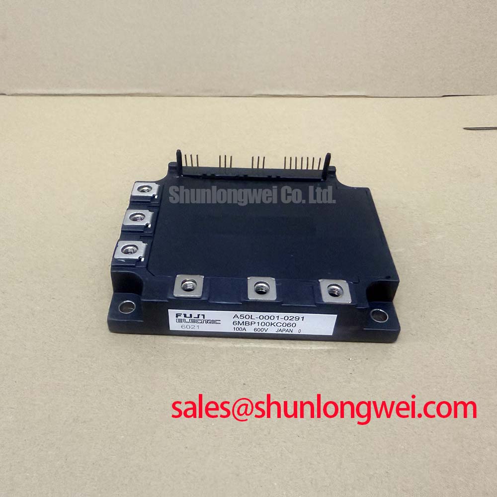
For a neutral reference on gate-loop construction, protection sequencing, and measurement discipline, consult Precision Gate Drive Design. A related module listing for 6MBP100KC060 can be placed beside the repair record for objective package, rating, and circuit-position comparison. It should not be treated as an automatic substitute until terminal arrangement, driver compatibility, mechanical fit, thermal conditions, and the original equipment documentation have been checked.
Assembly Integrity & Layout Architecture: Diagnosing Latent Gate-Emitter Dielectric Faults for 6MBP100RTB060
Cold, unpowered screening should start with the main terminals and the antiparallel diode path identified from the module’s terminal markings. Set the digital multimeter to diode-check mode, discharge the DC link, isolate the gate-drive connector, and compare the forward reading direction with the known-good reference unit. The purpose is not to assign an invented pass or fail voltage, but to detect an open path, an unexpected short, or a strong imbalance between equivalent terminals.
Next, check gate-to-emitter leakage with an instrument and range appropriate for the device and the test procedure. Do not apply an uncontrolled insulation tester directly to a gate terminal. A gate reading that changes after handling, cleaning, or cable reconnection should be investigated alongside connector contamination, probe pressure, moisture, and the condition of the driver board. Static measurements can identify a suspicious path, but they cannot reproduce switching stress or prove dynamic reliability.
🔧 Bench Diagnostic: Wear ESD protection and record the cold-state diode and leakage readings before installing the module, because a warm or energized comparison can conceal a wiring or assembly error.
Mechanical installation affects electrical behavior through contact pressure, thermal transfer, and parasitic inductance. Use the fastening method specified by the equipment or module documentation, apply a uniform mounting sequence, and keep the thermal interface clean and consistent. The correct torque is assembly-specific; a generic M5 torque value should not be presented as a Fuji Electric specification for this part.
Layout inspection should follow the current path rather than the schematic alone. Check the collector, emitter, and gate conductors for unintended shared impedance, confirm that the gate return reaches the intended emitter reference, and inspect the clearance around switching nodes and isolated control traces. At higher altitude or in contaminated environments, the system designer should review creepage, clearance, pollution conditions, insulation coordination, and enclosure protection using the applicable equipment standard. No FIT rate, single-event burnout threshold, cosmic-ray tolerance, or service-life figure is assigned here without an authoritative source.
For equipment returned from the field, compare the removed unit and replacement unit under identical cold conditions. Then perform a controlled low-energy gate-drive check before applying the full DC link. Confirm enable logic, fault reset, pulse polarity, and the absence of unintended gate activity. The Fuji Electric Power Semiconductors Portal is a suitable manufacturer reference point for broader product-family context, while the original equipment documentation remains the controlling source for terminal assignment and system-level operating limits.
Incoming Specification Record
| Item | Recorded value | Classification |
|---|---|---|
| Manufacturer | Fuji Electric | Official product identity |
| Model | 6MBP100RTB060 | Official product identity |
| Rated voltage | 600.0 V | Official Specification |
| Rated current | 100.0 A | Official Specification |
| Package | Fuji Power Module | Official physical parameter |